Sleeve and shield terminal manufacturing method

a manufacturing method and shield technology, applied in the direction of coupling device connection, coupling device details, connection formation by deformation, etc., can solve the problems of sleeve itself being crushed, sleeve may be partially crushed or cut, and insufficient flexural rigidity, etc., to achieve enhanced flexural rigidity (reaction force) of sleeve, prevent more reliably, and reduce the effect of crushing

Active Publication Date: 2021-09-30
SUMITOMO WIRING SYST LTD
View PDF8 Cites 0 Cited by
  • Summary
  • Abstract
  • Description
  • Claims
  • Application Information

AI Technical Summary

Benefits of technology

[0011]According to the first and second aspects of the invention, the convex portion bulges radially out over the entire circumference and is provided at the intermediate position of the sleeve in the axial direction. Thus, the flexural rigidity (reaction force) of the sleeve can be enhanced. This makes the sleeve hard to crush during the pressing of the barrel, and the insulating portion will not be compressed excessively by the sleeve. Particularly, since the convex portion is provided over the entire circumference of the sleeve, a circumferentially uniform compression force can be applied to the insulating portion and the sleeve will not bite into a circumferential part of the insulating portion.
[0012]According to the second aspect of the invention, the convex portion is crushed and elongated by the barrel. Thus, the insulating portion will not be compressed excessively by the convex portion.
[0014]An end convex portion may bulge radially out on an end part in the axial direction and may extend over an entire circumference and a concave portion may be formed between the end convex portion and the intermediate convex portion in the axial direction. According to this configuration, a convex-concave shape is formed by the end concave portion. The end convex portion and the concave portion are provided continuously on an end of the sleeve in the axial direction. Thus, the flexural rigidity of the sleeve is enhanced further and the insulating portion is prevented more reliably from being compressed excessively.
[0015]The barrel for pressing the convex portion may be configured to contact the shield. Accordingly, flexural rigidity of the sleeve is enhanced while preventing the insulating portion from being compressed excessively.

Problems solved by technology

Thus, a tip of each projection may strongly bite into the insulating portion and the insulating portion may be partially crushed or cut when the barrel is crimped.
In contrast, sufficient flexural rigidity may not be ensured with a general-purpose sleeve having a hollow cylindrical shape and a constant diameter over the entire length.
When the barrel is crimped, the sleeve itself may be crushed to compress the insulating portion excessively.

Method used


Image

  • Sleeve and shield terminal manufacturing method
  • Sleeve and shield terminal manufacturing method
  • Sleeve and shield terminal manufacturing method

Examples


Embodiment Construction

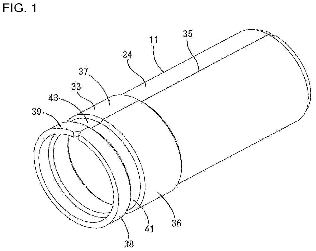
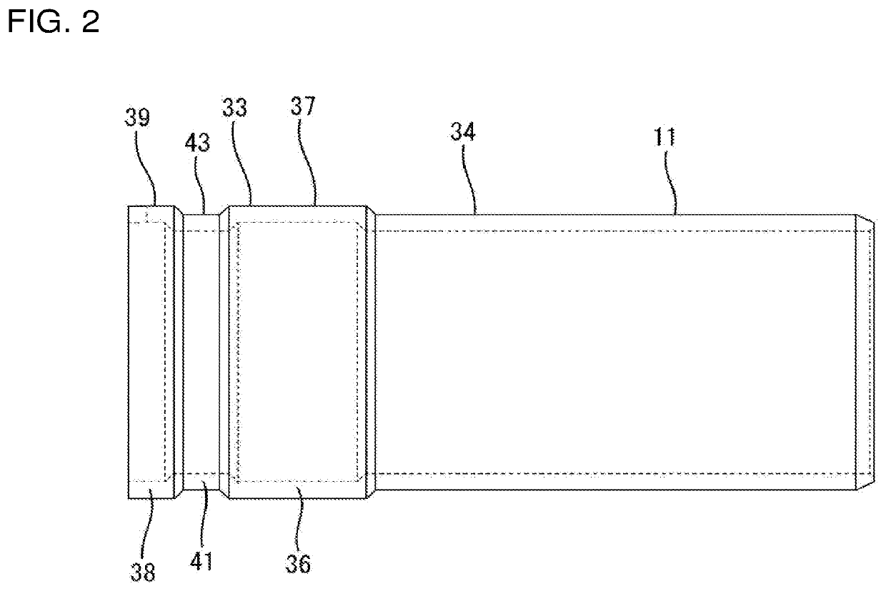
[0022]One embodiment of the invention is described with reference to FIGS. 1 to 6. A sleeve 11 of this embodiment is provided in a shield terminal 10 having a shielding function, and is connected to an end part of a shielded cable 60.

[0023]60>

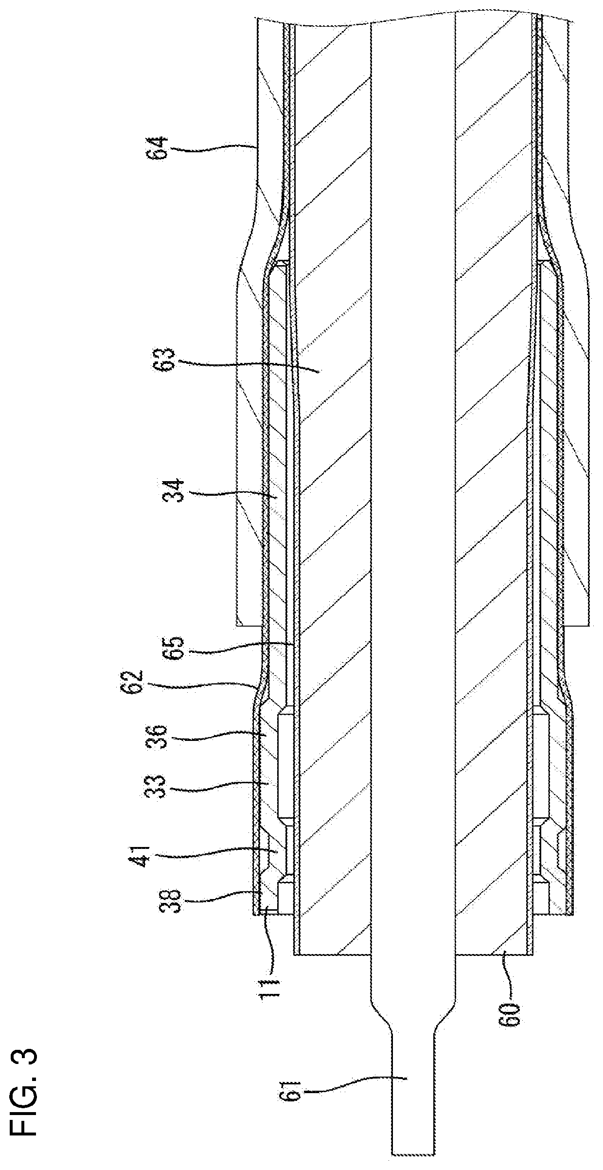
[0024]The shielded cable 60 is a coaxial cable and, as shown in FIGS. 3 and 4, includes a core 61 made of a conductor for transmitting a high-frequency signal, and a shield 62 made of a braided wire surrounds the core 61. An insulating portion 63 made of insulating resin covers the outer periphery of the core 61, and the shield 62 covers the outer periphery of the insulating portion 63. A sheath 64 made of insulating resin covers the outer periphery of the shield 62. In this embodiment, a layer of a metal foil 65, such as a copper foil, is provided between the insulating portion 63 and the shield 62. The layer of the metal foil 65 functions to adjust an impedance in a transmission path to a specified value.

[0025]The sheath 64 is removed in a pr...


PUM


Abstract

A sleeve (11) is a hollow cylindrical member provided in a shield terminal (10), and pressable by a wire barrel (18) by being arranged between an insulating portion (63) and a shield portion (62) of a shielded cable (60). A convex portion (36) shaped to bulge radially outward over an entire circumference is provided at an intermediate position of the sleeve (11) in an axial direction. The convex portion (36) is crushed and elongated by the wire barrel (18) of an outer conductor terminal (13). The insulating portion (63) can be prevented from being excessively compressed.

Description

CROSS-REFERENCE TO RELATED APPLICATIONS[0001]This application is a divisional of U.S. Patent Application No. 16 / 802,622, filed on February 27, 2020.BACKGROUND[0002]Field of the Invention. The invention relates to a sleeve and a shield terminal manufacturing method.[0003]Related Art. A shield terminal having a shielding function is connected to an end part of a coaxial cable (shielded cable). Japanese Unexamined Patent Publication No. 2010-232046 discloses a sleeve provided in a shield terminal. The sleeve is inserted between a braided wire and an insulating portion inside the braided wire on an end part of the shield terminal.[0004]The sleeve has a hollow cylindrical shape and is provided with projections at three positions spaced apart in a circumferential direction. The projections support the insulating portion at three points in the circumferential direction.[0005]A barrel is crimped to the sleeve together with the braided wire. Japanese Unexamined Patent Publication No. 2010-23...

Claims


Application Information

Patent Timeline
Patent Type & Authority Applications(United States)
IPC IPC(8): H01R9/05H01R43/048
CPCH01R9/0518H01R43/048H01R24/40H01R24/44H01R13/6581H01R43/04H01R2103/00H01R4/20H01R4/185
Inventor HASHIMOTO, NORIHITOKANEMURA, KEISUKEKUBOTA, MOTOKIKANG, LIPINGMITSUI, SHOHEIYAMANAKA, WATARUKASUGA, MASANOBUHIRANO, AIYAMADA, RYO
Owner SUMITOMO WIRING SYST LTD
Why Eureka
Try Eureka