Sound quality enhancement system and device

a technology of sound quality enhancement and enhancement system, applied in the direction of electrical transducers, low frequency amplifiers, gain control, etc., can solve the problems of increasing system participants, inability to solve problems, and inability to maintain latency, so as to achieve the effect of maintaining latency

Pending Publication Date: 2020-08-27
STEINBERG NEVIN +2
View PDF29 Cites 0 Cited by
  • Summary
  • Abstract
  • Description
  • Claims
  • Application Information

AI Technical Summary

Benefits of technology

[0020]A method of audio enhancement comprises the steps of: transmitting audio signals to an enhancement circuit, transmitting enhanced audio signals to a user, and maintaining latency between audio signal transmission and enhanced audio signal transmission below approximately 1.8 ms where 1.8 ms is the expected latency and, for certain other applications where delays are approximately 3.0 ms, below that 3.0 ms threshold.

Problems solved by technology

Prior attempts to rectify the issue of latency in sound monitoring have proven ineffective, are cost-inefficient, and unable to solve the problem.
Further, the monitor / controller 2 must be engaged in dynamic adjustment of the sound signal, which increases system participants and injects potentials for processing and other delays.
While the system exemplified by FIG. 2 may provide an analog, low-latency signal path in which feedback and acoustic latency are obviated by the elimination of the loudspeaker monitoring, it still requires monitor console equipment 6 and an monitor / controller 2 to operate, incurring additional costs and potential variability in sound processing.
Introduction of digital components into the architecture come with the cost of added throughput latency to the monitoring system due to digital signal routing and processing.
For theatrical applications, throughput latency in the aforementioned range may be deemed unusable for the performers.
As a further detriment to the system, an added digital monitor console 6A may further increase the latency time through the system and further disrupt and / or undermine the reliability of this monitoring solution.
For theatrical applications, this range of latency is unacceptably high for a performer.
Consequently, the systems exemplified by FIGS. 1 through 5 suffer from numerous deficiencies in terms of latency, increased resource utilization and / or additional controllers / monitors of the sound signal of the source, and / or redundancy in signal transmission components.

Method used


Image

  • Sound quality enhancement system and device
  • Sound quality enhancement system and device
  • Sound quality enhancement system and device

Examples


Embodiment Construction

[0036]In an exemplary embodiment of the invention, a circuit may be employed to eliminate all latency in the system by amplifying the sound signal and returning it directly to the performer's ears entirely in the analog domain. Consequently, signal degradation may be substantially eliminated and the need for additional equipment—analog or digital—is obviated. A further benefit according to this exemplary embodiment is the removal of any additional monitor / controller 2 from the system.

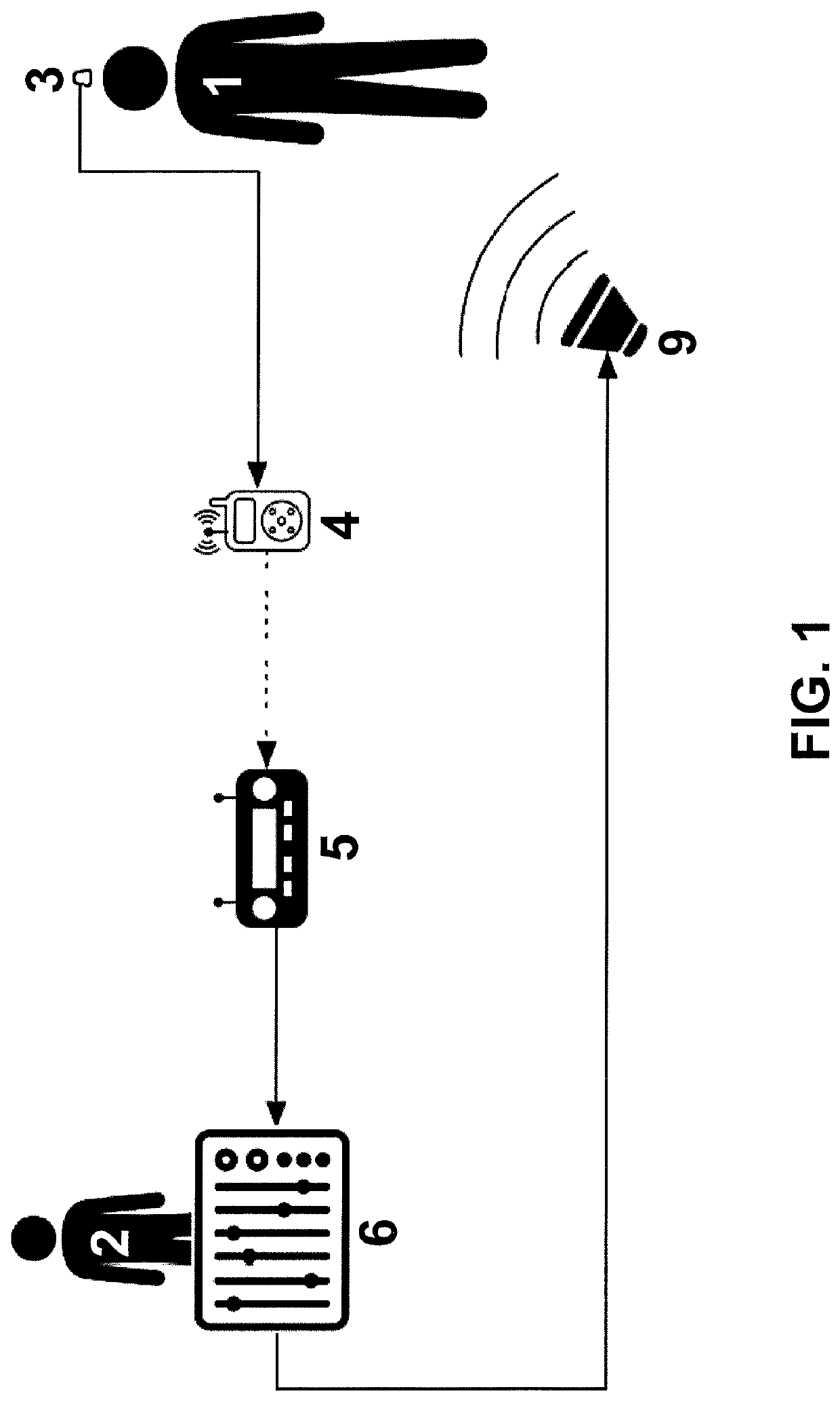
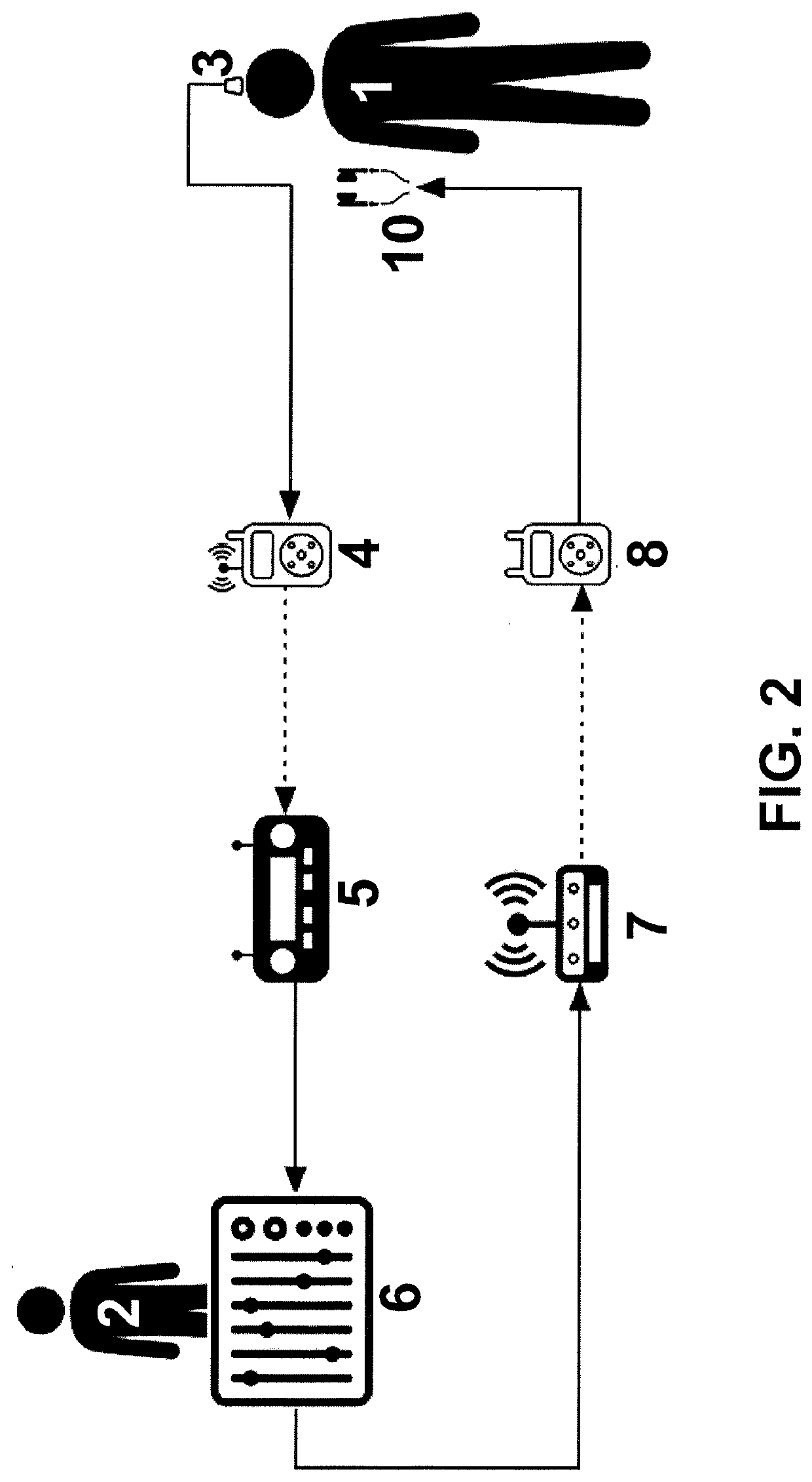
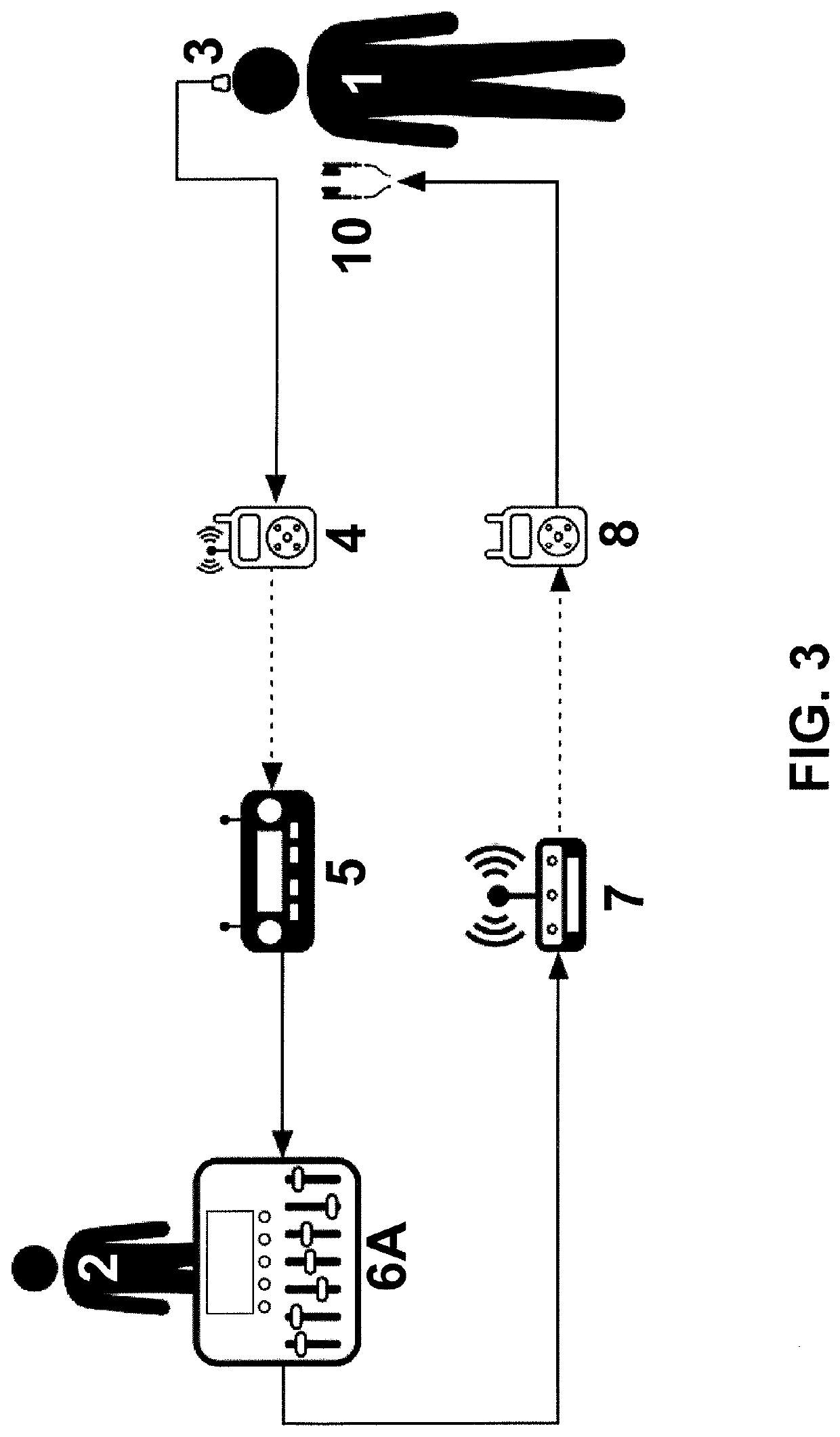
[0037]Referring to the illustrative embodiment of FIG. 6, the sound source 1 may use a sound input mechanism 3 to transmit sound to an analog / digital transmitter 4 / 4A to be received by an analog / digital receiver 5 / 5A. Before transmission to analog / digital transmitter 4 / 4A, the signal is received by a sound enhancement circuit, which may be exemplified by one or more of the embodiments related to or describing such an enhancement circuit 100, enhancement circuit 200, or their combinations and / or equivale...


PUM


Abstract

An exemplary audio enhancement system substantially eliminates latency by returning audio input signals in amplified form directly in the analog domain to the source, thereby reducing signal degradation and removing redundancy from digital and analog audio transmission and processing architectures.

Description

FIELD OF THE INVENTION[0001]This invention relates to systems that enhance sound quality and reception of audio signals while the sound is being received and communicated.BACKGROUND OF THE INVENTION[0002]In a typical audio signal flow, the mobile performer uses a wireless microphone transmitter whose receiver output is processed by a monitor system and returned to the performer by means of loudspeakers or wireless personal monitoring systems such as in-ear monitors (IEM's). This allows the performer to hear themselves relative to other sounds (music, audience, room, etc.). Typical microphones used may be cardioid (unidirectional) or omnidirectional. Challenges to any such monitoring system may include: (i) system throughput latency (as discussed in Lester and Boley article entitled “The Effects of Latency on Live Sound Monitoring,” Audio Engineering Society Convention paper (Oct. 5-8, 2007, New York, N.Y.)); (ii) signal degradation (electronic, acoustic); (iii) gain before feedback;...

Claims


Application Information

Patent Timeline
Patent Type & Authority Applications(United States)
IPC IPC(8): H03F3/185H03G3/32H03G9/00H04R29/00
CPCH04R29/007H03G3/32H03F3/185H03G9/005H03F3/45475H03F3/187H03F2200/03H03F3/68H03G3/02H04R29/004H04R3/00H03G3/10
Inventor STEINBERG, NEVINFUNK, ANDREWCRYSTAL, JASON
Owner STEINBERG NEVIN
Why Eureka
Try Eureka