Cylinder deactivation system and cylinder deactivation method
- Summary
- Abstract
- Description
- Claims
- Application Information
AI Technical Summary
Benefits of technology
Problems solved by technology
Method used
Image
Examples
Embodiment Construction
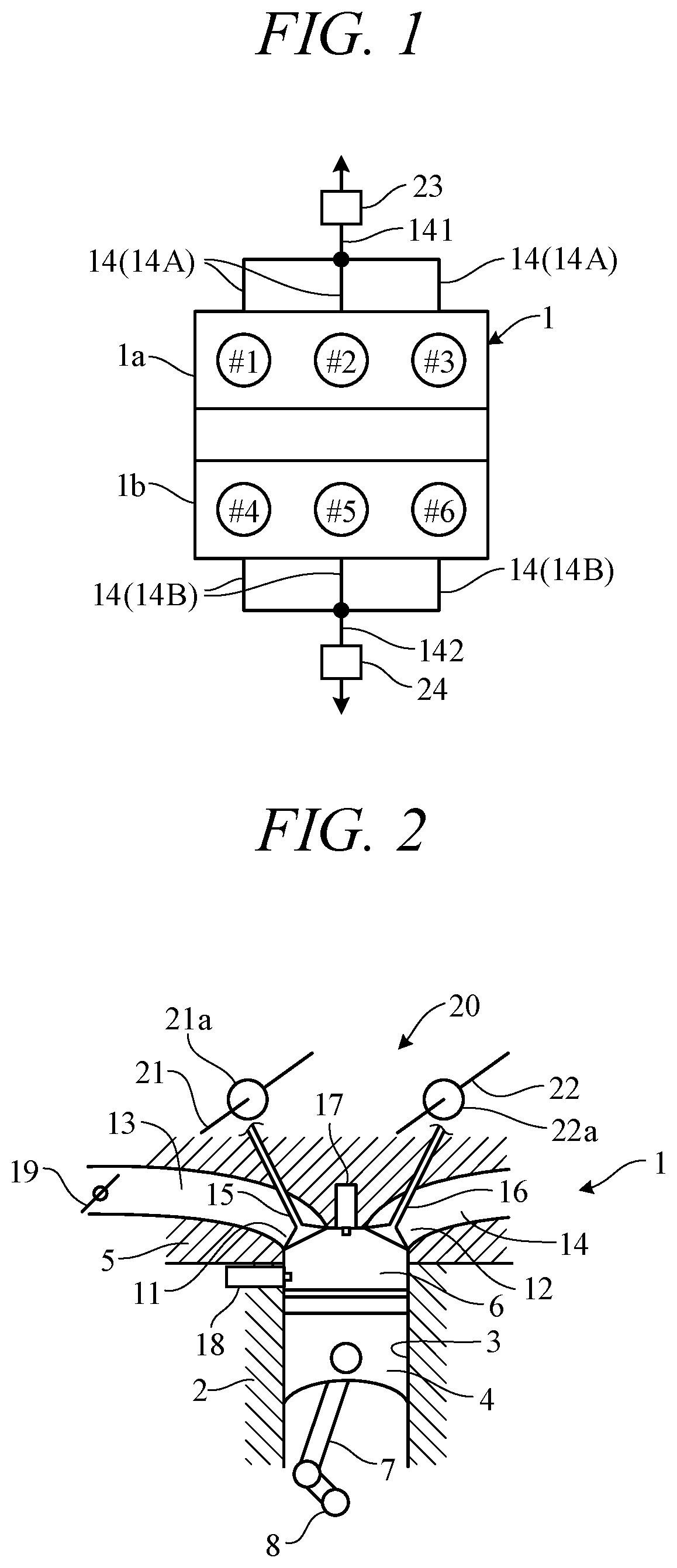
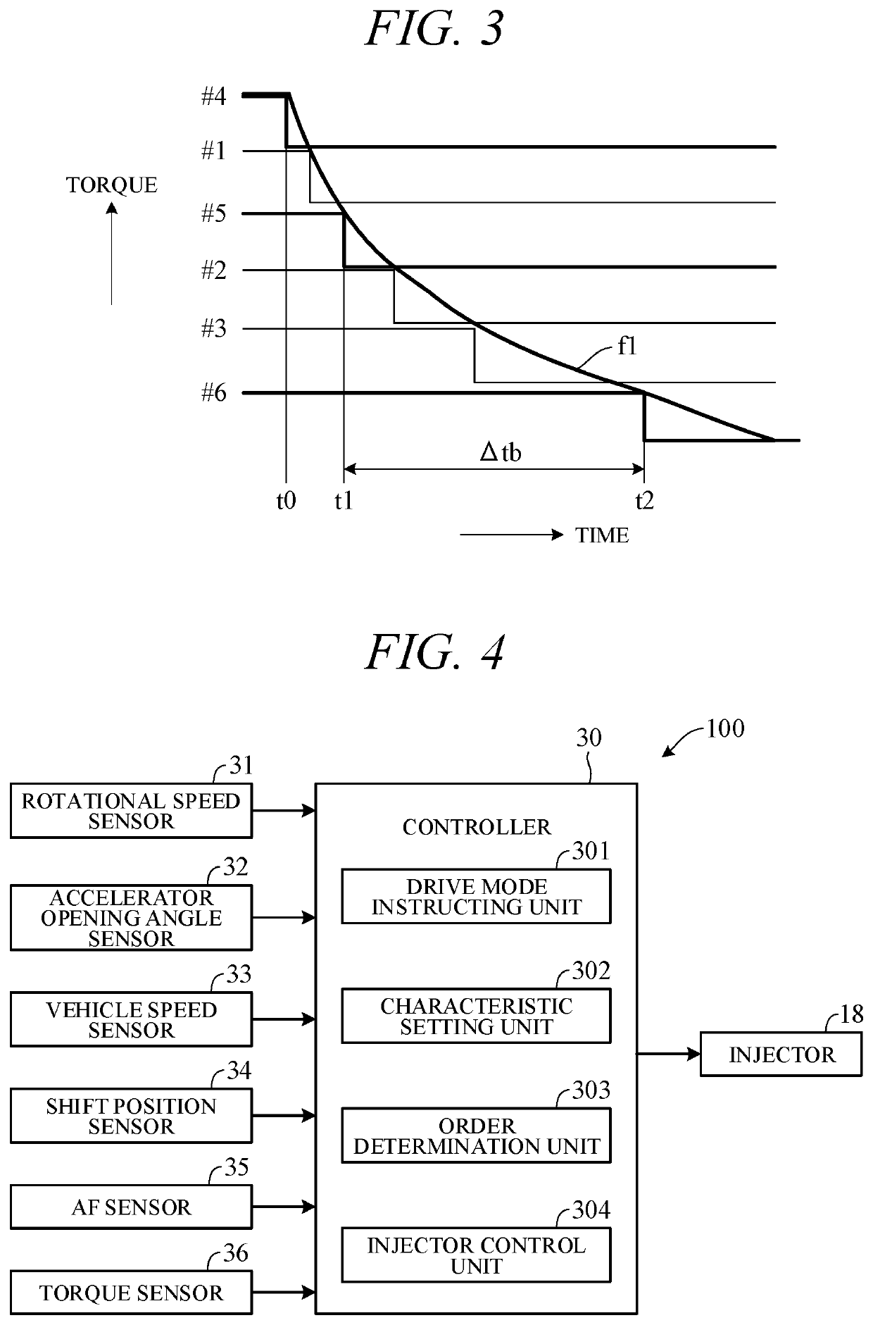
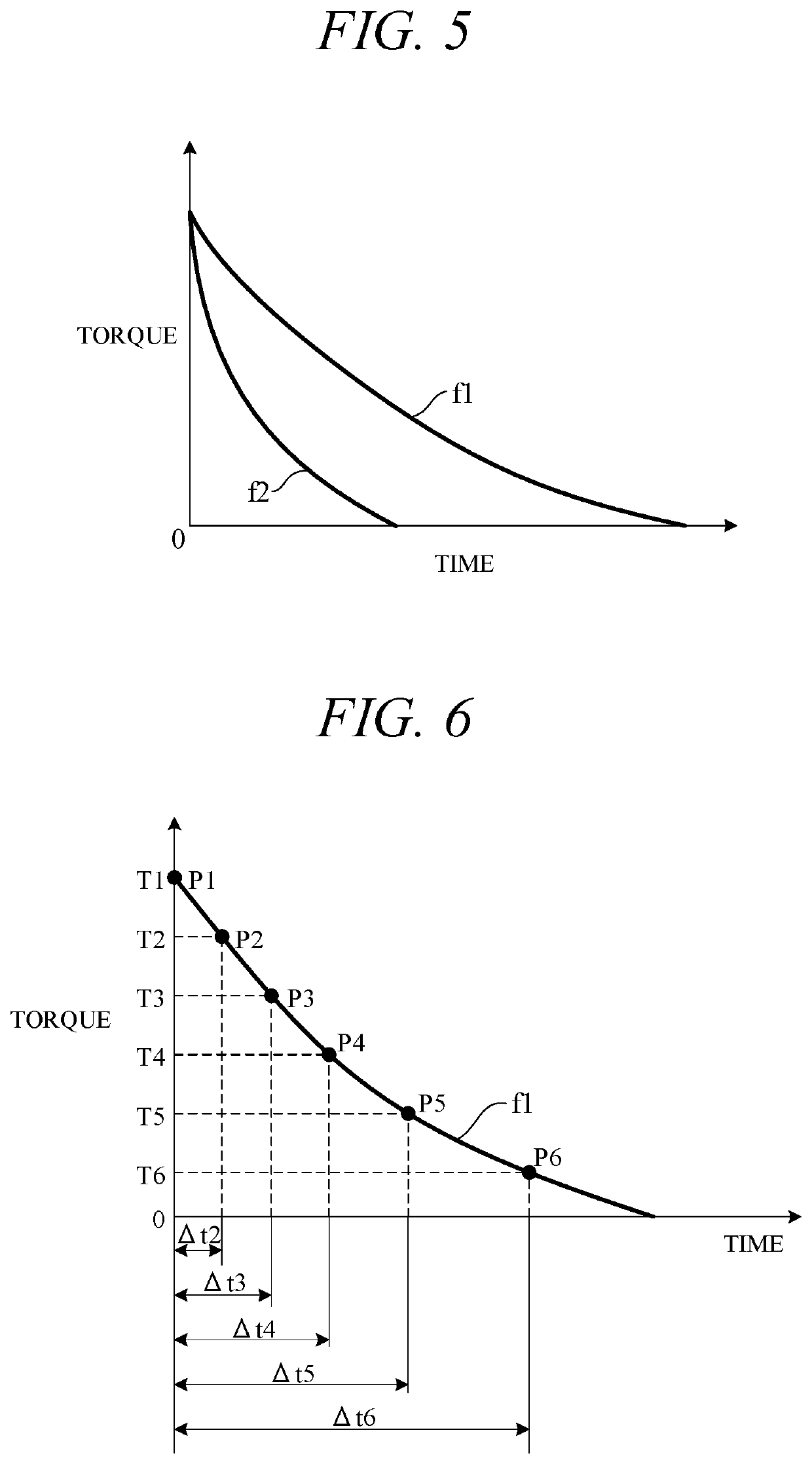
[0016]Now, an embodiment of the present invention will be described with reference to FIGS. 1 to 9. A cylinder deactivation system according to the embodiment of the present invention is applied to an engine that is a spark-ignition internal combustion engine having a fuel cut function of stopping fuel supply to multiple cylinders during decelerated travel or the like of the vehicle. For example, this engine is a V-6 engine where multiple cylinders are disposed in a V-shape in a side view and a pair of front and rear banks are formed and is also a four-cycle engine that undergoes four strokes of intake, expansion, compression and exhaust in one operation cycle. Note that the engine may be an engine where a pair of left and right banks are formed.
[0017]FIG. 1 is a drawing showing the position of multiple (six) cylinders 1 to 6 of an engine 1. The engine 1 includes three cylinders 1 to 3 belonging to a front side bank (front bank) 1a and three cylinders 4 to 6 belonging to a rear side...
PUM
 Abstract
Description
Claims
Application Information
 - R&D
- Intellectual Property
- Life Sciences
- Materials
- Tech Scout
- Unparalleled Data Quality
- Higher Quality Content
- 60% Fewer Hallucinations
Browse by: Latest US Patents, China's latest patents, Technical Efficacy Thesaurus, Application Domain, Technology Topic, Popular Technical Reports.
© 2025 PatSnap. All rights reserved.Legal|Privacy policy|Modern Slavery Act Transparency Statement|Sitemap|About US| Contact US: help@patsnap.com


