Integrated fuel cell and heat engine hybrid system for high efficiency power generation

a fuel cell and heat engine technology, applied in the direction of machines/engines, electrochemical generators, fuel cells containing electrolytes, etc., can solve the problems of reducing efficiency, increasing the hardware cost of power plants, and reducing efficiency, so as to achieve high system efficiencies

Active Publication Date: 2008-08-07
FUELCELL ENERGY INC
View PDF42 Cites 101 Cited by
  • Summary
  • Abstract
  • Description
  • Claims
  • Application Information

AI Technical Summary

Benefits of technology

[0015]In the disclosed system, the anode exhaust gas, optionally, is cooled and the product water is removed by a condenser. The cooled anode exhaust gas containing residual fuel not utilized in the fuel cell is then optionally compressed in a gas compressor and thereafter flows to a combustor or oxidizer forming a part of the heat engine assembly and which also receives heated compressed oxidant gas. The gas compressor boosting of the pressure of the anode exhaust gas helps bring the pressure of the gas output of the oxidizer up to the inlet pressure of the expansion cycle or section of the gas turbine of the heat engine assembly. The anode exhaust gas is then oxidized in the oxidizer and the output of the oxidizer including heated compressed oxidant gas is supplied to the expansion cycle or section of the gas turbine of the heat engine assembly. This results in a mechanical power output from the expansion section and an exhaust gas comprising oxidant gas which is then used as the oxidant gas for the cathode section of the fuel cell.
[0016]Also, in the disclosed system, the oxidant supply gas is compressed or pressurized in the compressor section or cycle of the heat engine assembly and is optionally heated in the heat recovery unit by the cathode exhaust gas to which, as above-mentioned, the heat recovery unit is responsive. This compressed heated oxidant supply gas then flows to the oxidizer or combustor of the heat engine assembly, as also above-mentioned. With the hybrid system, therefore, the recovery of waste heat from the fuel cell combined with the oxidation of the anode exhaust gas in the heat engine assembly results in very high system efficiencies.
[0017]In certain cases, supplemental air from a blower is combined with the exhaust gas from the expansion section of the gas turbine before it is fed to the cathode section of the fuel cell. The combined gas ensures a required cathode flow for both the oxidant gas and the removal of waste heat from the fuel cell.

Problems solved by technology

In this arrangement, the fuel cell is operated at a high pressure, which substantially increases the cost of the power plant hardware.
The high pressure operation of the fuel cell inhibits the use of internal reforming in the fuel cell which further increases the plant cost and reduces efficiency, and subjects the fuel cell to potentially damaging pressure differentials in the event of plant upset.
Furthermore, the fuel cell pressure is coupled with the gas turbine pressure, reducing the reliability of operation and limiting the application to system designs where the gas turbine pressure is nearly matched with the fuel cell pressure.
Despite the benefits provided by the system of the '988 patent, there are limitations to its application.
However, they require a relatively high temperature heat exchanger, which may be very costly especially for large-scale power plants (>10 MW).

Method used


Image

  • Integrated fuel cell and heat engine hybrid system for high efficiency power generation
  • Integrated fuel cell and heat engine hybrid system for high efficiency power generation
  • Integrated fuel cell and heat engine hybrid system for high efficiency power generation

Examples


Embodiment Construction

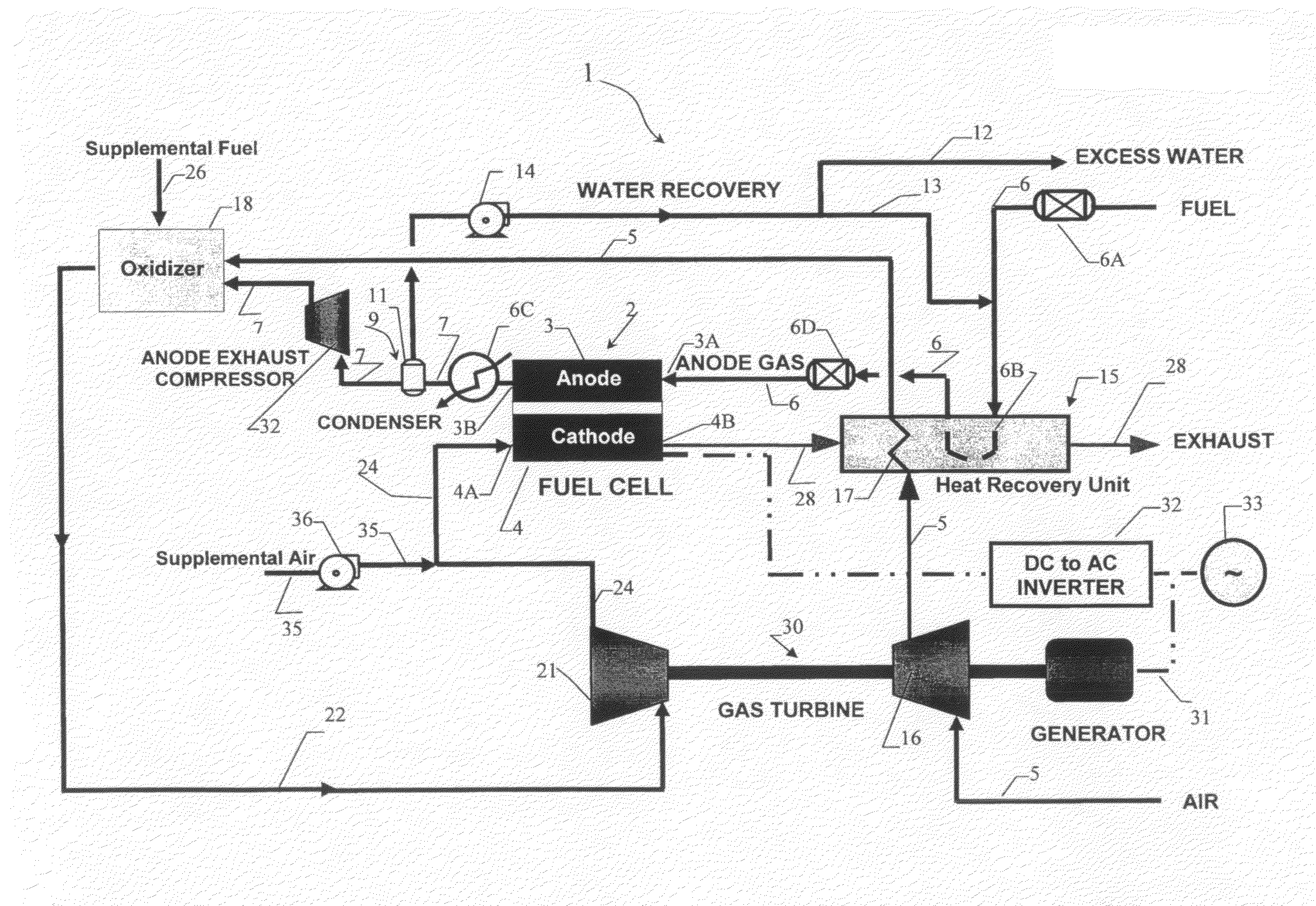
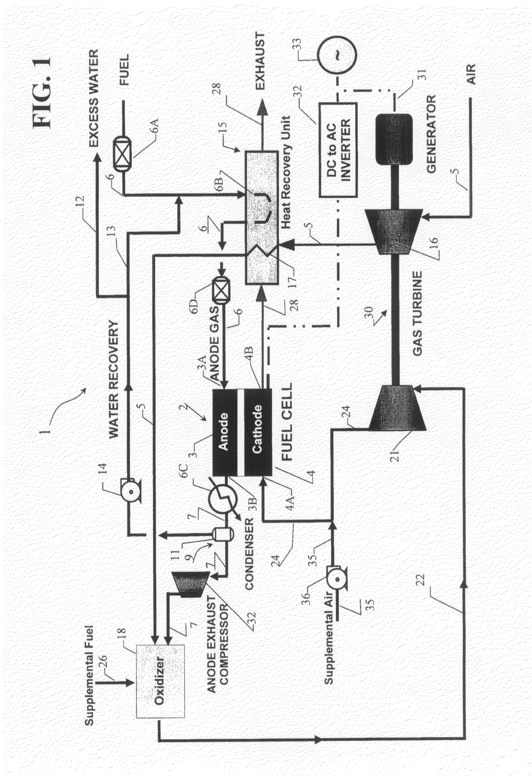
[0021]FIG. 1 shows a block diagram of a hybrid fuel cell and heat engine system 1 for supplying power to a load. The system 1 comprises a high-temperature fuel cell 2 and a heat engine assembly 30. The fuel cell 2 includes an anode compartment 3 and a cathode compartment 4 separated by an electrolyte matrix. The anode compartment 3 is adapted to receive fuel from a fuel supply path 6 and to output anode exhaust. The cathode compartment 4 is adapted to receive oxidant gas and to output cathode exhaust. The hybrid system also optionally includes a water transfer assembly 9 for transferring water in the anode exhaust to the fuel supply path 6 and for outputting water-separated anode exhaust.

[0022]The fuel cell 2 can be any type of high temperature fuel cell such as a molten carbonate fuel cell or solid oxide fuel cell.

[0023]The heat engine assembly 30 can include any variety of the Internal Combustion Engine such as a combustion turbine, a 4-cycle spark ignited (SI) reciprocating engin...


PUM

PropertyMeasurementUnit
temperatureaaaaaaaaaa
pressureaaaaaaaaaa
poweraaaaaaaaaa

Abstract

A fuel cell and heat engine hybrid system using a high-temperature fuel cell having an anode compartment adapted to receive fuel from a fuel supply path and to output anode exhaust gas and a cathode compartment adapted to receive oxidant gas and to output cathode exhaust gas. A heat engine assembly is adapted to receive oxidant gas and a further gas comprising one of the anode exhaust gas and a gas derived from the anode exhaust gas and to cause oxidation of the further gas and generate output power, the heat engine also generating heat engine exhaust including oxidant gas. The heat engine exhaust is then used to provide oxidant gas to the cathode compartment of the fuel cell.

Description

CROSS-REFERENCE TO RELATED APPLICATIONS[0001]This application is a non-provisional application based on and claiming the benefit of the filing date of U.S. Provisional Patent Application Ser. No. 60 / 888,186, filed Feb. 5, 2007, the entire disclosure of which is incorporated herein by reference.BACKGROUND OF THE INVENTION[0002]This invention relates to fuel cell production systems and, in particular, to a fuel cell system integrated with a heat engine such as an internal combustion engine and an external combustion engine.[0003]A fuel cell is a device, which directly converts chemical energy stored in hydrocarbon fuel into electrical energy by means of an electrochemical reaction. Generally, a fuel cell comprises an anode electrode and a cathode electrode separated by an electrolyte, which serves to conduct electrically charged ions.[0004]A fuel cell may be combined with a heat engine such as a turbine generator to produce a high efficiency system, commonly called a hybrid system. In...

Claims


Application Information

Patent Timeline
Patent Type & Authority Applications(United States)
IPC IPC(8): H01M8/00
CPCF02C1/007Y02E60/525F02C3/36F02G1/04H01M8/04014H01M8/04097H01M8/04111H01M8/04141H01M8/04164H01M8/04171H01M8/0662H01M8/14H01M8/2495H01M2008/1293H01M2008/147H01M2250/20H01M2250/402Y02B90/12Y02E20/14Y02E60/526Y02T90/32F02C3/22Y02B90/10Y02E60/50Y02T90/40F02C6/00F02C6/18H01M8/04H01M8/06
Inventor GHEZEL-AYAGH, HOSSEIN
Owner FUELCELL ENERGY INC
Why Eureka
Try Eureka