Filtering graphical program elements based on configured or targeted resources

a technology of graphical program elements and resources, applied in the field of graphical programming and measurement and automation systems, can solve the problems of user programming skills and ability to interact with the computer system often becoming a limiting factor in the achievement of optimal utilization of the computer system, complex task of programming a computer system to model or implement a process often, and user's inability to fully grasp techniques, etc., to achieve the effect of reducing the effort required, simplifying the configuration process, and preventing incompatible vi/

Active Publication Date: 2006-10-10
NATIONAL INSTRUMENTS
View PDF6 Cites 95 Cited by
  • Summary
  • Abstract
  • Description
  • Claims
  • Application Information

AI Technical Summary

Benefits of technology

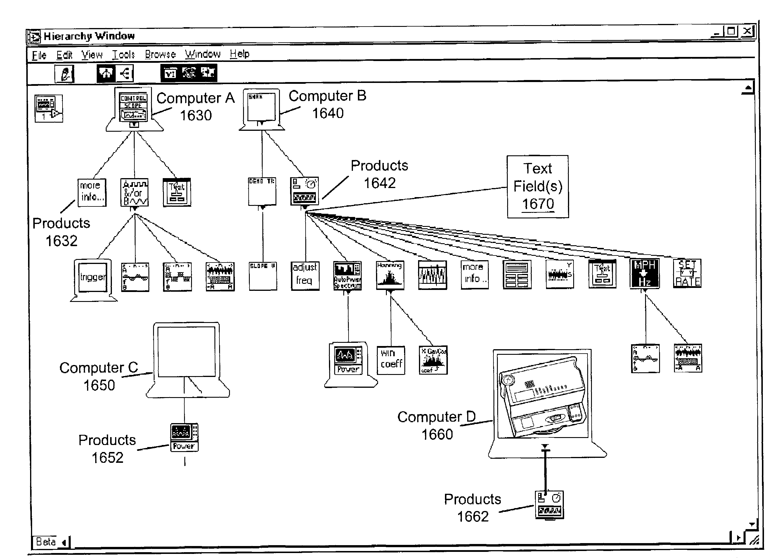
[0038]In one embodiment, the filtering of graphical elements may be applied to VI references. In particular, interaction with controls and indicators of a VI running asynchronously may be managed while the values read and written are strictly typed to the data type of the control. This approach may eliminate the overhead associated with dynamic invocation, and may thus improve efficiency of the system. This approach may be particularly useful in communicating with FPGA targeted VIs, where the overhead of dynamic calls in relation to the number of parameters passed in fast control loops entails significant overhead. Additionally, FPGA VI's often have more controls and indicators than are supported by a connector pane, thereby preventing the use of the call by reference node for those attributes not included in the connector pane. However, it should be noted that the approach described below is not limited to FPGA applications, but is broadly applicable to multi-platform development and use, providing a generic means for communication with graphical programs running on a variety of platforms with improved code readability. For example, in contrast to the prior art methods where a VI reference node may be dynamically typed, e.g., typed to a connector pane, at run time, the VI references may be statically bound to a specific VI.
[0040]In response to user input selecting the option to select a target VI for the open reference node, a graphical user interface, e.g., a dialog box, may be presented for receiving user input specifying the target VI, for example, a text entry field for entering a path, or a browsing mechanism which allows the user to browse the system (or other networked systems) for the target VI. Thus, the open reference node may be typed at “edit time”, and may thence be configured in the graphical program without the risks associated with run time typing.
[0044]If the VI selection made on the open reference node is changed, the refnum output by that node may change appropriately. In response to this change in type, any access nodes (read, write, or property nodes) connected to the refnum terminal may change their respective refnum outputs and check the new refnum type against their selected controls. If any of the selected control names are no longer valid, the corresponding terminal may be removed from the node and the wire connected from that terminal may be invalidated, breaking the diagram. In this manner, the user may never have an invalid configuration selected on their diagram. Thus, the static typing of the open reference node to that of the selected VI may prevent errors in the configuration of VIs in the graphical program which do not become apparent until run time. Additionally, the explicit selection of the target platform for the VI may provide a means for target specific syntax checking, thereby preventing incompatible VI / platform configurations.
[0045]Thus, various embodiments of the systems and methods described above may be used to simplify the configuration process for a user of a measurement system or any other system which employs graphical elements to configure a graphical diagram and / or controls and devices used by the graphical diagram. The graphical diagram may be a graphical program or a configuration diagram. More specifically, various embodiments of the systems and methods described herein allow a user to specify any of a variety of options for filtering the displayed attributes of a graphical programming element in the graphical diagram, thereby reducing the effort required by the user to configure controls and / or devices associated with the graphical element. Thus, in various embodiments, the present invention provides various embodiments of a system and method for filtering attributes of graphical program elements in a graphical program or configuration diagram based upon configured and / or targeted software and / or devices in the system.

Problems solved by technology

When traditional text-based programming environments are used, the user's programming skills and ability to interact with the computer system often become a limiting factor in the achievement of optimal utilization of the computer system.
There are numerous subtle complexities which a user must master before he can efficiently program a computer system in a text-based environment.
The task of programming a computer system to model or implement a process often is further complicated by the fact that a sequence of mathematical formulas, steps or other procedures customarily used to conceptually model a process often does not closely correspond to the traditional text-based programming techniques used to program a computer system to model such a process.
Since a user often is not fully proficient in techniques for programming a computer system in a text-based environment to implement his solution, the efficiency with which the computer system can be utilized often is reduced.
Traditional users of these systems, however, often were not highly trained in programming techniques and, in addition, text-based programming languages were not sufficiently intuitive to allow users to use these languages without training.
Therefore, implementation of such systems frequently required the involvement of a programmer to write software for control and analysis of instrumentation or industrial automation data.
Thus, development and maintenance of the software elements in these systems often proved to be difficult.
Alternatively, the front panel may be used merely to view the input and output, or just the output, and the input may not be interactively manipulable by the user during program execution.
However, due to the potentially overwhelming number of possible attributes which may be presented to the user, it is often difficult and / or tedious for the user to sort through the possible attributes (icons or items) to locate those which are germane to the task at hand.
These reference nodes are generally typed dynamically, i.e., at run time, and so there may be some risk of type conflicts which may not be apparent until the program is executed.

Method used


Image

  • Filtering graphical program elements based on configured or targeted resources
  • Filtering graphical program elements based on configured or targeted resources
  • Filtering graphical program elements based on configured or targeted resources

Examples


example use cases

[0123]In some cases, a selected option may be invalid for a given context. In one embodiment, these invalid option selections may be detected by the system, and a more suitable option automatically selected. Below are described several use cases illustrating invalid options and example responses.

use case # 1

Use Case #1

[0124]User has no configured devices and decides to select either option 1 (show attributes for configured devices), or option 3 (show attributes for selected devices). In this case since there are no devices configured, the system may display a warning box indicating that the option is invalid, and the option may be set to option 2 (show all attributes).

use case # 2

Use Case #2

[0125]User has two devices (A & B) configured and the user selects option 2 (show all attributes). However, the user then deselects all the devices from the list. In this case a warning may be displayed indicating that the option is invalid, and the option may be set to option 1 (show attributes for configured devices).


PUM


Abstract

System and method for filtering attributes of a graphical program element (GPE) in a graphical program or diagram, e.g., a property node, menu, property page, icon palette, etc., based on targeted or configured resources. Input is received specifying or selecting a filter option from presented filter options. The filter options include 1) display all attributes of the GPE; 2) display attributes of the GPE associated with configured resources; and 3) display attributes of the GPE associated with selected configured resources. User input is received to access the GPE. Attributes for the GPE associated with the resources are retrieved from the database and displayed in accordance with the selected filtering option. The filtered attributes of the element are then selectable by a user for various operations, e.g., to configure the graphical program, to configure resources, to initiate a purchase or order for the resources, and / or to install the resources, among others.

Description

FIELD OF THE INVENTION[0001]The present invention relates to the fields of graphical programming and measurement and automation systems, and more particularly to a system and method for filtering attributes of graphical program elements in a graphical program based on configured or targeted hardware and / or software resources in the system.DESCRIPTION OF THE RELATED ART[0002]Scientists and engineers often use measurement or automation systems to perform a variety of functions, including measurement of a physical phenomena or unit under test (UUT), test and analysis of physical phenomena, simulation, hardware-in-the-loop testing, process monitoring and control, control of mechanical or electrical machinery, data logging, laboratory research, and analytical chemistry, to name a few examples.[0003]A typical measurement system comprises a computer system with one or more measurement devices or measurement hardware. The measurement device may be or include a computer-based instrument, a d...

Claims


Application Information

Patent Timeline
Patent Type & Authority Patents(United States)
IPC IPC(8): G06F15/00G06F13/00G06F9/44
CPCG06F8/34
Inventor SHAH, BIRENTHORNE, STEPHENNOVACEK, MATTHEW
Owner NATIONAL INSTRUMENTS
Why Eureka
Try Eureka