
System and method for enhanced combustion control in an internal combustion engine

Inactive Publication Date: 2002-05-23
NISSAN MOTOR CO LTD
View PDF0 Cites 99 Cited by
  • Summary
  • Abstract
  • Description
  • Claims
  • Application Information

AI Technical Summary

Problems solved by technology

Accordingly, operating conditions under which auto-ignited combustion may be performed are restricted to a limited engine speed and load range.
Auto-ignited combustion, if performed under operation conditions outside of this limited range, may cause the engine to knock or suffer from unstable combustion.
Rapid cylinder pressure elevation, if not too excessive to cause the engine to knock, may result in making an unacceptably high level of combustion noise.
With this known technique, operating conditions under which auto-ignited combustion may be performed remain restricted to such engine speed and load range where the air / fuel mixture charge will not be ignited before TDC during compression stroke.
They cause the increased probability for engine to knock at high engine speeds and / or high loads, making it difficult to extend operating conditions, under which auto-ignited combustion may be performed, toward high engine speeds and / or high loads.

Method used


Image

  • System and method for enhanced combustion control in an internal combustion engine
  • System and method for enhanced combustion control in an internal combustion engine
  • System and method for enhanced combustion control in an internal combustion engine

Examples


Embodiment Construction

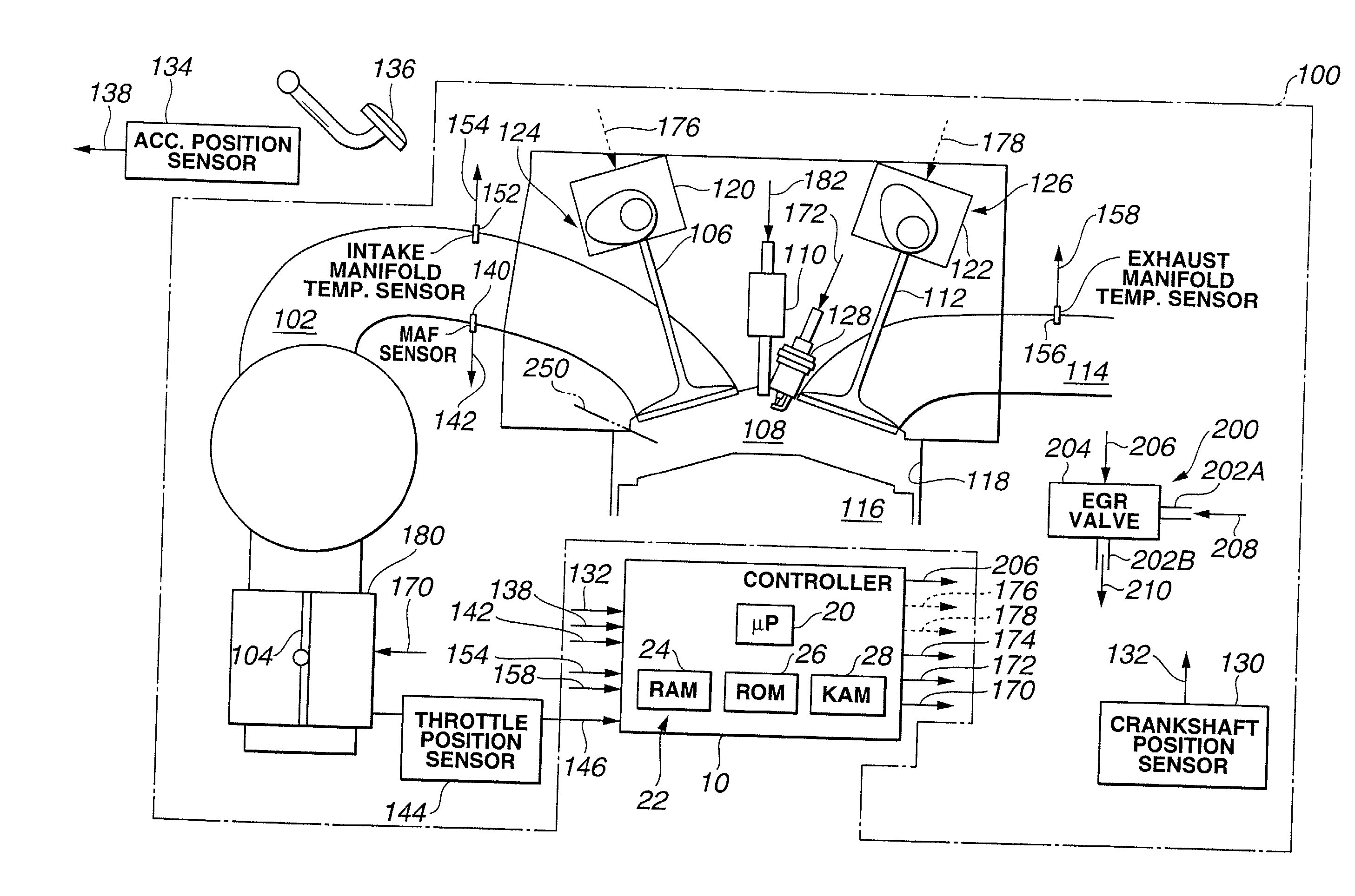
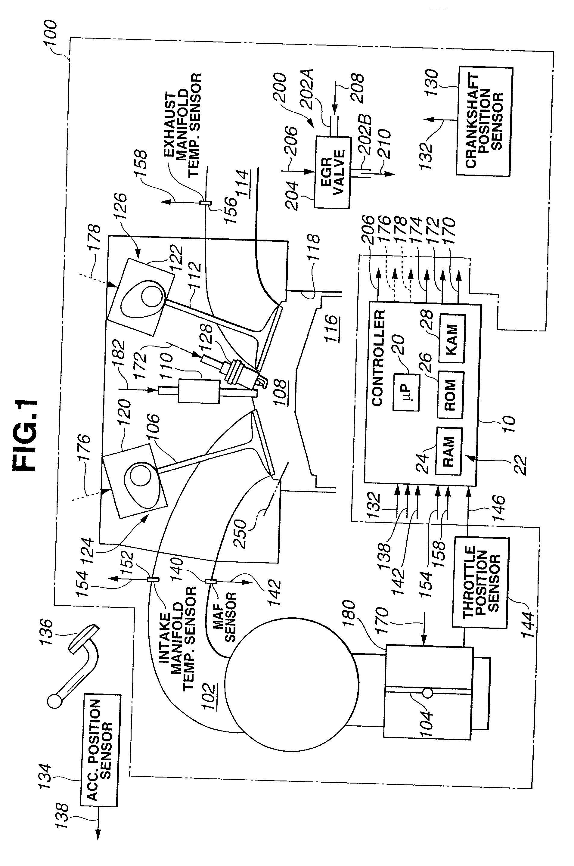
[0041] FIG. 1 shows an electronic engine controller (ECC) 10 and an internal combustion engine 100, which comprises a plurality of cylinders, one of which is shown in FIG. 1. Engine 100 draws an intake air charge through intake manifold 102 past a throttle plate 104, and intake valve 106 and into combustion chamber 108. An air / fuel mixture, which consists of the air charge and gasoline fuel injected by fuel injector 110 of a fuel injection device, is ignited in combustion chamber 108, and exhaust gas resulting from combustion of the air / fuel mixture is transported past exhaust valve 112 through exhaust manifold 114. A piston 116 is coupled to a crankshaft, not shown, and moves in a linear fashion within a cylinder defined by cylinder walls 118.

[0042] Valve controllers 120 and 122 are provided to actuate intake and exhaust valves 106 and 112. In a preferred embodiment, intake valve 106 and valve controller 120 constitute an inlet control device 124 for controlling flow of intake air ...


PUM


Abstract

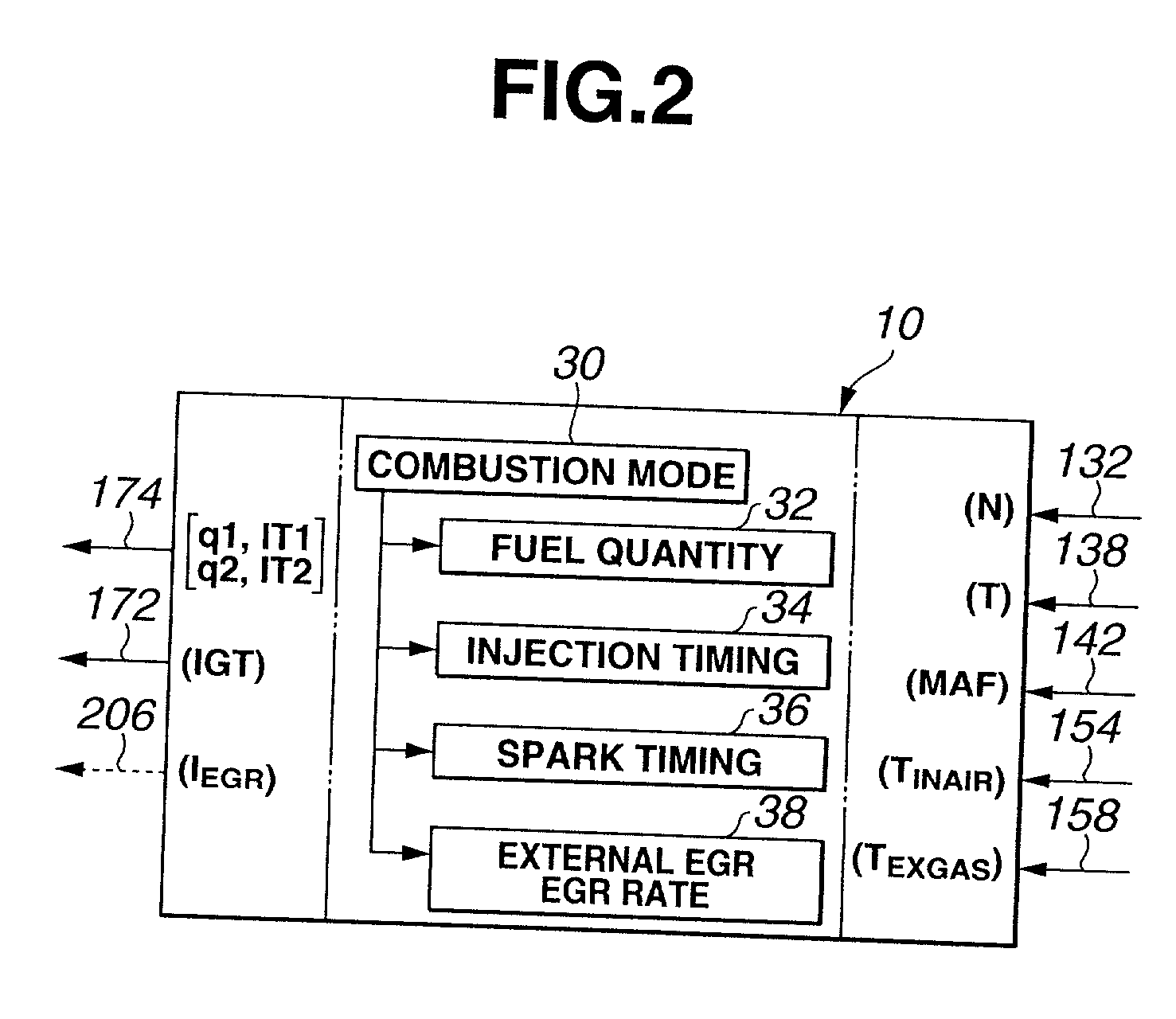
A system and method for enhanced combustion control in an internal combustion engine is disclosed. A fuel supply system has a fuel injector positioned to directly inject fuel into a combustion chamber, and it is capable of performing a split injection wherein a first fuel injection in each engine cycle precedes a second fuel injection that occurs during compression stroke in the same engine cycle. A spark plug produces a spark to ignite a first air / fuel mixture portion created due to the second fuel injection, initiating a first stage combustion. The first stage combustion raises temperature and pressure high enough to cause auto-ignition of a second air / fuel mixture portion surrounding the first air-fuel mixture portion, initiating a second stage combustion. An engine controller is programmed to perform control over initiation timing of the second stage combustion in response to at least one of the engine speed and load. This control is accomplished by varying at least one of a fuel injection timing of the first fuel injection, a fuel injection timing of the second fuel injection, spark timing, a proportion of fuel quantity of the second fuel injection to the total fuel injected in each engine cycle, and an EGR rate in response to at least one of engine speed and load.

Description

[0001] 1. Field of the Invention[0002] The present invention relates to a system and method for enhanced combustion control in an internal combustion engine.[0003] 2. Description of Related Art[0004] In a 4-stroke cycle gasoline injected internal combustion engine, when certain conditions are met within a charge of lean air / fuel mixture, auto-ignition can occur wherein bulk combustion takes place initiated simultaneously from many ignition sites within the charge. This results in very stable power output, very clean combustion and high thermal efficiency. NOx emission produced in auto-ignited combustion is extremely low in comparison with spark-ignited combustion. In spark-ignited combustion, the burnt gas temperature is highly heterogeneous within the charge with very high local temperature values, creating high NOx emission. By contrast, in controlled auto-ignited combustion where the combustion is uniformly distributed throughout the charge from many ignition sites, the burnt gas...

Claims


Application Information

Patent Timeline
IPC IPC(8): F02P5/15F02B1/12F02B3/04F02B11/00F02B23/10F02D13/02F02D21/08F02D37/02F02D41/00F02D41/02F02D41/04F02D41/30F02D41/38F02D41/40F02D43/00F02M25/07
CPCF02B1/12Y02T10/47F02B23/101F02D13/0265F02D37/02F02D41/005F02D41/006F02D41/0065F02D41/3011F02D41/3041F02D41/3047F02D41/401F02D41/402Y02T10/44F02B3/04F02D35/028F02D2200/101Y02T10/40
Inventor YAMAGUCHI, KOICHIURUSHIHARA, TOMONORIYOSHIZAWA, KOUDAITANIYAMA, TSUYOSHI
Owner NISSAN MOTOR CO LTD
Learn More