Shock testing apparatus and method

a technology of shock testing apparatus and shock waveform, which is applied in the direction of measurement devices, structural/machine measurement, instruments, etc., can solve the problems of fixed infrastructure, limited approximation of desired undex shock waveform, and limited range of shock environment replicable, so as to mitigate the displacement of the float and the impact table, mitigate the displacement of the top, and reduce the energy of the fluid

Pending Publication Date: 2020-09-03
THORNTON TOMASETTI DEFENCE LTD
View PDF5 Cites 3 Cited by
  • Summary
  • Abstract
  • Description
  • Claims
  • Application Information

AI Technical Summary

Benefits of technology

[0020]Optionally, the spacing of the airgun support frame or frames from the base of the tank is adjustable by means of variable height spacers which raise and lower the support frame. In this way, the spacing of the airgun(s) from the float can be adjusted.
[0036]Optionally, the stop members of the channel-section guide members are configured to prevent the box structure of the impact table from extending further into the tank and to maintain the bedplate of the impact table at a minimum height above the tank's open end.
[0044]Optionally, to further control and constrain the motion of the impact table following impact of the float, the shock testing apparatus comprises a second damping means which acts on the impact table externally of tank to arrest the downward motion of the impact table, i.e. to decelerate the impact table, during downward travel following impact.
[0048]Optionally, to mitigate displacement of the float and the impact table as a result of air bubble expansion from the airgun(s), the air emanating from the airguns is vented around the sides of the float and towards the open end of the tank.
[0049]Optionally, to mitigate fluid overflowing the top of the tank and / or to reduce the energy of fluid disturbed by the airguns, baffles are provided around an upper portion of the tank, and optionally around the box structure of the impact table.

Problems solved by technology

Individual equipments and systems may be tested on impact type machines, but these require a fixed infrastructure, and can only provide a limited approximation to the desired UNDEX shock waveform.
Swing hammer type shock testing machines, such as those disclosed in U.S. Pat. No. 6,990,845 B2 and U.S. Pat. No. 5,003,811 A), or machines where rotary motion is converted into a shock input (such as US 20160258837 A1 and U.S. Pat. No. 5,355,716) can provide only a simplistic approximation of an UNDEX event and are typically limited to the range of shock environments that they can replicate.

Method used


Image

  • Shock testing apparatus and method
  • Shock testing apparatus and method
  • Shock testing apparatus and method

Examples


Embodiment Construction

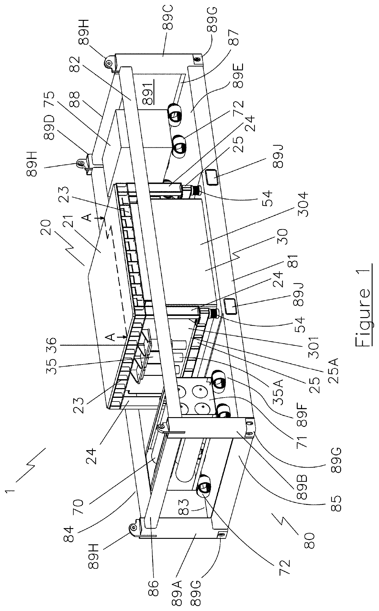
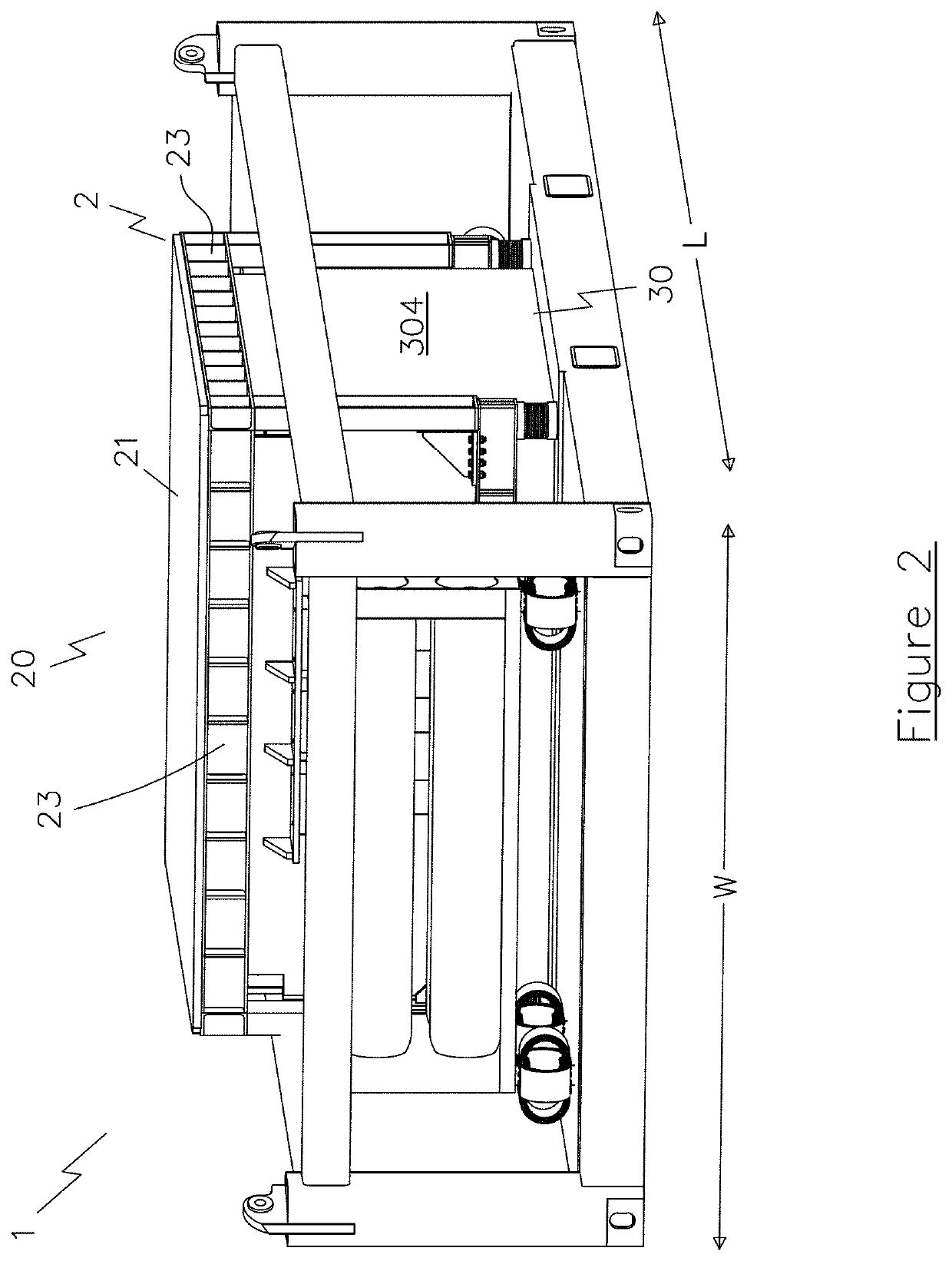
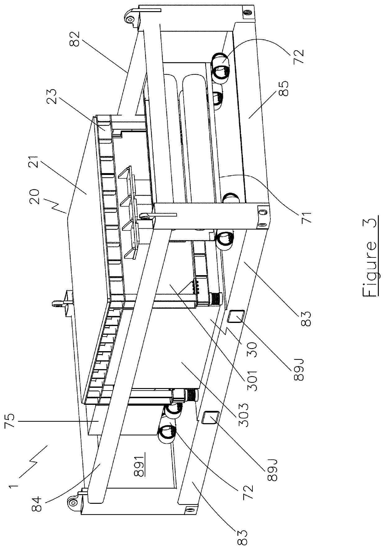
[0082]With reference to FIGS. 1 to 3 and 5 to 8 there are shown examples of a shock testing apparatus 1 in accordance with the invention comprising an impact table 20 for supporting an object to be tested, a tank 30, a float 40 (FIGS. 4a, 4b, 7, 8) and a plurality of airguns 50 (FIGS. 4a, 4b, 7, 8).

[0083]With reference to FIG. 4a, impact table 20 is a stiffened structure comprising a bedplate 21 and a box structure 22 which depends from the underside of the bedplate 21. Box structure 22 is a stiffened structure having a plurality of sidewalls 221, 222, 223, 224 and a baseplate 225. Baseplate 225 is provided with an impactor plate 226 on its underside, i.e. at the bottom of, and external to, the box structure 22. Impactor plate 226 is arranged to contact a corresponding impactor plate 404 provided on a float 40 located within tank 30 as described below. Preferably the impact table is of steel construction.

[0084]The underside of bedplate 21 is provided around its perimeter with a plur...


PUM


Abstract

A shock testing apparatus comprising:an impact table for supporting an object to be tested;a tank;at least one float;one or more airguns;wherein the at least one float is arranged to float upon a fluid held within the tank and is movable within the tank to impact the impact table in response to the firing of the one or more airguns.

Description

FIELD OF THE INVENTION[0001]The present invention relates generally to a portable method of shock testing equipment using seismic airguns to simulate the effects of shocks, such as but not limited to, underwater explosions (UNDEX), in order to assess and prove the robustness of a tested item to mechanical shock of a variety of forms and severities.BACKGROUND TO THE INVENTION[0002]Shock testing is used in many different engineering environments to demonstrate the robustness and resilience of equipment or systems to a mechanical shock. The type of mechanical shock input may range from a simple robustness low acceleration criteria for handling and transportation of a single item, to a complex and high severity shock pulse applied to a functioning system, for example a diesel generator or a large computer system.[0003]Warships are designed to be robust against underwater explosions (UNDEX), and to demonstrate that a warship has met the required standard of shock capability, a number of ...

Claims


Application Information

Patent Timeline
Patent Type & Authority Applications(United States)
IPC IPC(8): G01M7/08
CPCG01M7/08G01M10/00G01N3/307
Inventor THOMPSON, PHILLIP R.COLLIAR, GAVINWHATLEY, ALEXANDERHUTCHISON, STUART
Owner THORNTON TOMASETTI DEFENCE LTD
Why Eureka
Try Eureka