
Eureka
For R&D, Eureka makes reading and utilizing patents & technical documents easy.
Eureka AIR
Designed for self-driven R&D workflows. Generate viable solutions, solve complex R&D challenges, empower your innovation with AI.

Eureka Materials
Designed for material experts only. Revolutionize your material R&D, from search, analyze, to developing new materials.

TechResearch
Generate reliable direction feasibility study reports for your R&D in just a few steps.

TechSeek
Discover and master advanced knowledge NOW. Basics, ideas, possibilities, all at once.

TechMind
As an expert in R&D Theories, TechMind can generates customized viable solutions instantly.

TechRisk
Analyze your overall solution with one click, know your potential R&D risks in advance.

TechMonitor
Get weekly tech updates, stay abreast of the latest tech innovations and key insights.
Image forming apparatus
- Summary
- Abstract
- Description
- Claims
- Application Information
AI Technical Summary
Benefits of technology
Problems solved by technology
Method used
Image

Examples
embodiment 1
1. Overall Structure and Operation of Image Forming Apparatus
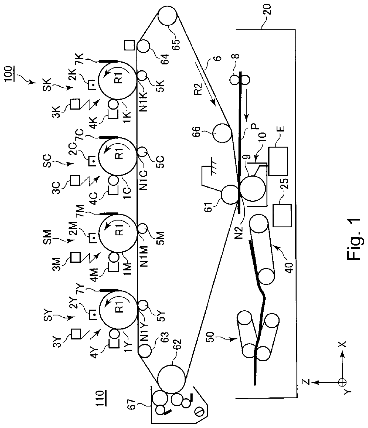
[0028]FIG. 1 is a schematic sectional view of the image forming apparatus 100 in this embodiment. By the way, a direction indicated by an arrow mark Y in FIG. 1 is roughly parallel to the rotational axis of the photosensitive drum 1 and that of the secondary transfer roller 9. The photosensitive drum 1 and secondary transfer roller 9 will be described later. A direction indicated by an arrow mark X in the drawing is such a direction that is perpendicular to the direction indicated by the arrow mark Y. Here, it is assumed to be roughly parallel to the horizontal direction. Further, a direction indicated by an arrow mark Z in the drawing is such a direction that is perpendicular to the direction indicated by the arrow mark X, and the direction indicated by the arrow mark Y, in the drawing. Here, it is assumed to be roughly parallel to the gravity direction (vertical direction). Further, the front side in terms of the directi...
embodiment 2
[0068]Next, one of the other embodiments of the present invention is described. The image forming apparatus in this embodiment is the same in basic structure and operation as the one in the first embodiment. Therefore, the components of the image forming apparatus in this elements, and the portions thereof, which are the same in function and / or structure as the counterparts in the first embodiment are given the same referential codes as the counterparts, and are not going to be described.
[0069]In the first embodiment, the secondary transferring member was such a roller that directly contacts the intermediary transfer belt 6. In this embodiment, the secondary transferring member comprises an endless belt, and a secondary transfer roller which has a function of a suspending-tensioning roller (support roller) by which the belt is suspended. The image forming apparatus is structured so that the secondary transfer roller is pressed against the intermediary transfer belt 6, with the prese...
PUM
 Abstract
Description
Claims
Application Information
 - R&D Engineer
- R&D Manager
- IP Professional
- Industry Leading Data Capabilities
- Powerful AI technology
- Patent DNA Extraction
Browse by: Latest US Patents, China's latest patents, Technical Efficacy Thesaurus, Application Domain, Technology Topic, Popular Technical Reports.
© 2024 PatSnap. All rights reserved.Legal|Privacy policy|Modern Slavery Act Transparency Statement|Sitemap|About US| Contact US: help@patsnap.com