Knob and input device

a technology of input device and knob, which is applied in the field of knobs, can solve problems such as the difficulty of operating a touch panel-equipped display, and achieve the effect of preventing the occurrence of non-detection and erroneous detection of a touch of a finger on the knob

Active Publication Date: 2020-09-03
MITSUBISHI ELECTRIC CORP
View PDF0 Cites 7 Cited by
  • Summary
  • Abstract
  • Description
  • Claims
  • Application Information

AI Technical Summary

Benefits of technology

[0008]According to the present invention, the occurrence of non-detection a

Problems solved by technology

Since each touch panel-equipped display does not have an uneven shape on a surface thereof, it is difficult to

Method used


Image

  • Knob and input device
  • Knob and input device
  • Knob and input device

Examples


embodiment 1

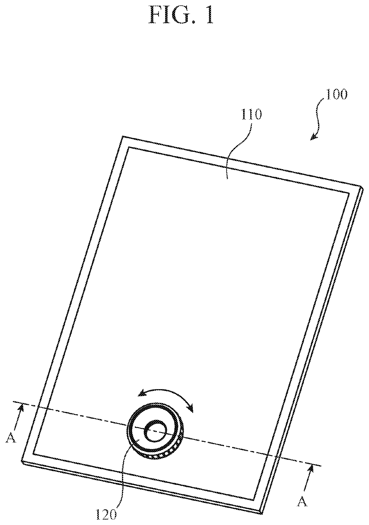
[0020]FIG. 1 is a perspective view of an input device 100 according to Embodiment 1.

[0021]The input device 100 includes a touch panel-equipped display 110 and a knob 120. The touch panel-equipped display 110 includes a capacitive type touch panel 111 (hereinafter referred to as “touch panel 111”), and a display (not illustrated). The display is integral with the touch panel 111.

[0022]The knob 120 is fixed onto the touch panel 11l. The knob 120 is shaped like a ring. The knob 120 is constructed in such a way as to be rotatable in directions of a double-headed arrow shown in FIG. 1. Since the touch panel 111 is exposed inside a ring in the knob 120, information displayed on the display can be visually recognized.

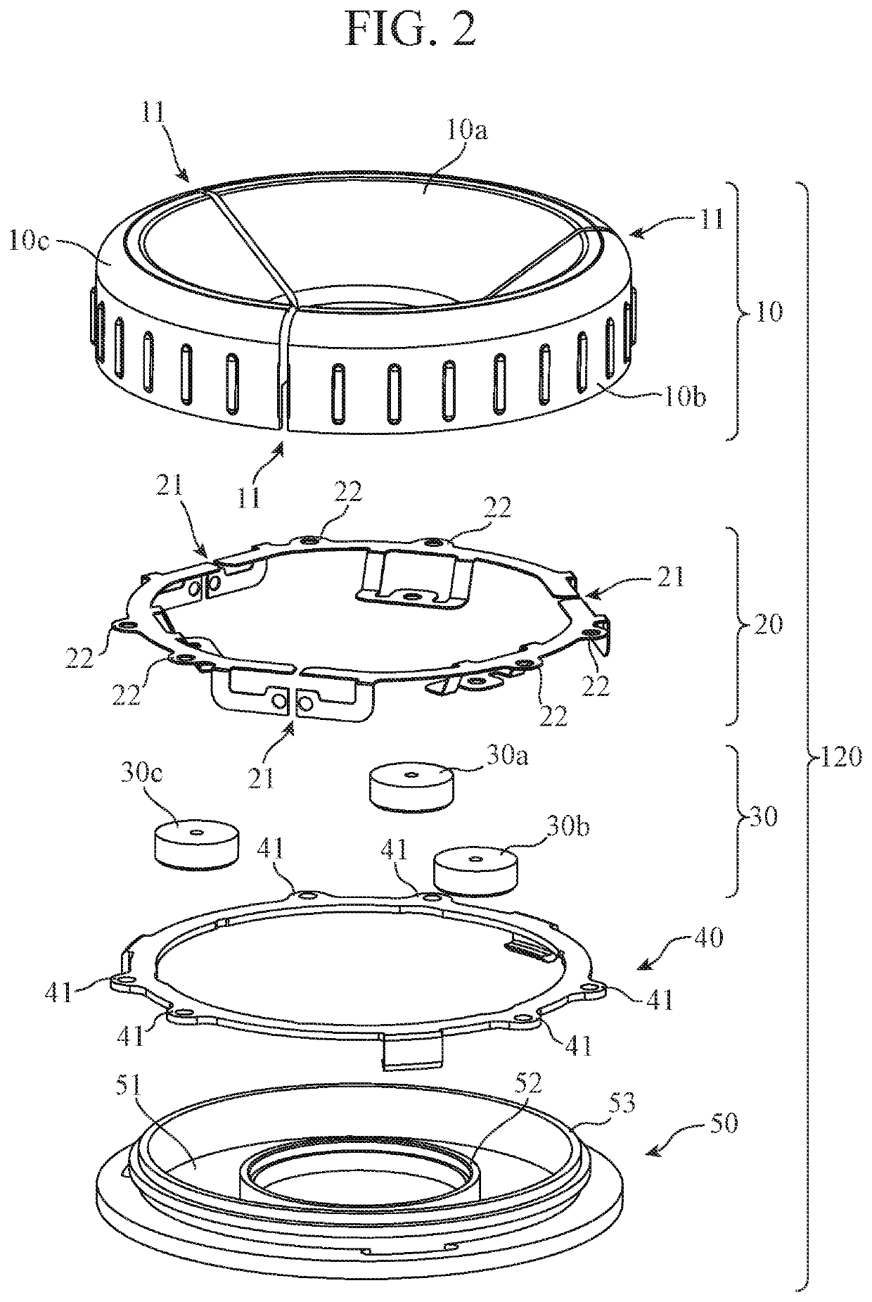
[0023]FIG. 2 is an exploded view of the knob 120 according to Embodiment 1.

[0024]The knob 120 mainly includes an operation portion 10, a conductive connecting member 20, conducting terminal portions 30, a rotary member 40, and a rotary supporting member 50.

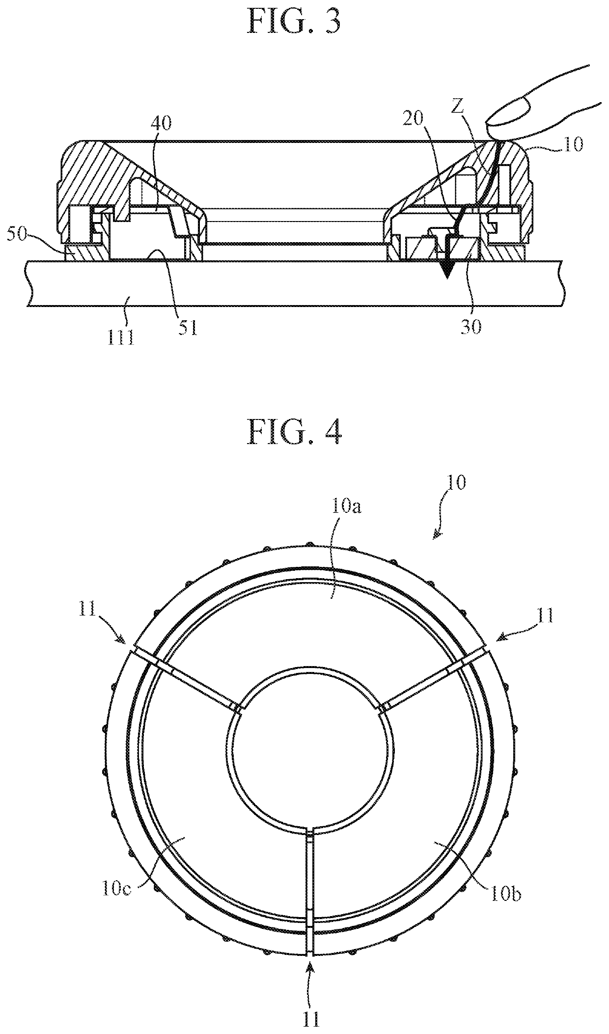
[0025]FIG. 3 is a cr...

embodiment 2

[0059]FIG. 7 is an exploded view of a knob 120 according to Embodiment 2.

[0060]FIG. 8 is a diagram in which an operation portion 10 of the knob 120 according to Embodiment 2 is viewed from an upper surface.

[0061]There is a difference in operation portion dividing portions 11 between the knob 120 according to Embodiment 1 and the knob 120 according to Embodiment 2. Hereinafter, an explanation of components having the same functions as those of the components explained in Embodiment 1 or components having like functions will be omitted or simplified.

[0062]In Embodiment 2, the operation portion dividing portions 11 are referred to as the operation portion dividing portions 11A. The operation portion dividing portions 11A do not physically divide the operation portion 10, unlike the operation portion dividing portions 11 according to Embodiment 1.

[0063]The operation portion dividing portions 11A are non-conductive areas formed in the operation portion 10. The operation portion dividing ...

embodiment 3

[0067]FIG. 9 is an exploded view of a knob 120 according to Embodiment 3.

[0068]There is a difference in conducting terminal portions 30 between the knob 120 according to Embodiment 1 and the knob 120 according to Embodiment 3. Hereinafter, an explanation of components having the same functions as those of the components explained in Embodiment 1 or components having like functions will be omitted or simplified.

[0069]In Embodiment 1, the case in which the conducting terminal portions30 are comprised of the first conducting terminal portion 30a, the second conducting terminal portion 30b, and the third conducting terminal portion 30c is explained. The first conducting terminal portion 30a, the second conducting terminal portion 30b, and the third conducting terminal portion 30c have the same diameter.

[0070]In Embodiment 3, conducting terminal portions 60 are used instead of the conducting terminal portions 30. The conducting terminal portions 60 are comprised of a first conducting ter...


PUM


Abstract

It includes: an operation portion comprised of a ring-shaped conductive member, a rotational operation being performed on the operation portion; a rotary supporting member comprised of a ring-shaped non-conductive member and fixed onto a capacitive type touch panel, the rotary supporting member rotatably supporting the operation portion; a ring-shaped concave groove disposed in the rotary supporting member; and conductive conducting terminal portions electrically connected to the operation portion, the conductive conducting terminal portions being rotated inside the concave groove integrally with the operation portion, positions of the conducting terminal portions being detected by the touch panel, wherein the operation portion is divided into a plurality of areas electrically insulated from each other in a circumferential direction, and at least two of the conducting terminal portions are mounted to different areas of the plurality of areas.

Description

TECHNICAL FIELD[0001]The present invention relates to a knob for operating a touch panel, and an input device in which the knob is fixed to the touch panel.BACKGROUND ART[0002]In recent years, many displays each with a capacitive type touch panel (hereinafter each referred to as “touch panel-equipped display”) have been adopted for navigation devices, audio devices, center displays, and so on which are mounted in vehicles. Since each touch panel-equipped display does not have an uneven shape on a surface thereof, it is difficult to operate a touch panel-equipped display unless this touch panel-equipped display is being visually recognized.[0003]Patent Literature 1 discloses an input device in which a knob is fixed to a touch panel-equipped display in order to improve the ease of operation of the touch panel-equipped display. The knob includes a gripping portion for allowing a user to perform an operation, and a terminal portion that serves as a contact surface for the touch panel. W...

Claims


Application Information

Patent Timeline
IPC IPC(8): G06F3/0362G06F3/041G06F3/044
CPCG06F3/0362G06F3/0412G06F3/044G06F3/0338
Inventor TAKAOKA, SHINYATSUKAGUCHI, AKINORI
Owner MITSUBISHI ELECTRIC CORP
Why Eureka
Try Eureka