Method and system for object recognition via a computer vision application

a computer vision and object recognition technology, applied in the field of object recognition via computer vision applications, can solve the problems of limiting visibility affecting the detection effect of objects, etc., and achieves the effects of facilitating computer vision applications, and reducing the difficulty of detection

Active Publication Date: 2020-09-03
BASF COATINGS GMBH
View PDF0 Cites 4 Cited by
  • Summary
  • Abstract
  • Description
  • Claims
  • Application Information

AI Technical Summary

Benefits of technology

[0069]It is known in the art that having engineered features that can be easily defined and detected is the most computationally efficient way of identifying objects visually in comparison to other techniques. For example, by the scanning of a barcode, a system immediately connects to a database to identify the object being scanned. Similarly, the proposed system is even more efficient due to its ability to identify discrete fluorescence spectral patterns in the spectral dimension of an image like a barcode reader operates in the spatial dimension. The number of spectral characters is independent of the shape of the object of interest. This enables the proposed system and method to not be limited in number of classifications to geometry / shape of objects. Objects with the same shape and even same color can be distinguished by analyzing the fluorescence chemistry extracted by the computer vision system.
[0070]One of the key aspects of the invention is that ambient lighting elements can be utilized as light probes for the proposed system and method. Indoor conditions usually require a controlled and uniform lighting environment to be present to facilitate computer vision applications. However, the proposed system and method capitalize on the differences of lighting conditions to recognize objects instead. Furthermore, one unique aspect of the system is that it utilizes a rapid change of ambient lighting from a LED light source or comparable arrangements to extract fluorescence chemistry information from a respective object. The rapid changing of such lighting conditions is not visible to human eyes and the spectral changes of lighting sources can be managed by the system through a network, working in sync with the sensor's integration times. Multiple light sources connected to the network can be synced to have the same temporal and spectral change frequencies amplifying the effect.
[0071]Another unique aspect of the invention is that the fluorescence (or chemistry) information of the objects can be coupled to information about that object, i.e. type of material, price, manuals, etc. and information held at the dynamic (live) database, i.e. the data storage unit that tracks and updates the information in 3D maps. By dynamically tracking the objects in 3D space using the proposed system and potentially in combination with other methods, the proposed system would enable the ability to distinguish two identical objects by 3D location of those objects for as long as the object locations are dynamically updated, and the objects are in field of view of the sensor of the proposed system.

Problems solved by technology

One challenge in computer vision field is being able to identify as many objects as possible within each scene with high accuracy and low latency using a minimum amount of resources in sensors, computing capacity, light probe etc.
Furthermore, the barcodes etc. on flexible items may be distorted, limiting visibility.
This could be a problem for example when a barcode on an object on the shelf at a store is to be scanned.
Technique 2: Upconversion pigments have limitations in viewing distances because of the low level of emitted light due to their small quantum yields.
They are usually opaque and large particles limiting options for coatings.
Further complicating their use is the fact that compared to fluorescence and light reflection, the upconversion response is slower.
While some applications take advantage of this unique response time depending on the compound used, this is only possible when the time of flight distance for that sensor / object system is known in advance.
Similarly viewing angle dependent pigment systems only work in close range and require viewing at multiple angles.
Also, the color is not uniform for visually pleasant effects.
Color-based recognitions are difficult because the measured color depends partly on the ambient lighting conditions.
Luminescence based recognition under ambient lighting is a challenging task, as the reflective and luminescent components of the object are added together.
Technique 3: Electronic tags such as RFID tags require the attachment of a circuit, power collector, and antenna to the item / object of interest, adding cost and complication to the design.
Technique 4: These active methods require the object of interest to be connected to a power source, which is cost-prohibitive for simple items like a soccer ball, a shirt, or a box of pasta and are therefore not practical.
Flexible objects that can change their shape are problematic as each possible shape must be included in the database.
There is always inherent ambiguity as similarly shaped objects may be misidentified as the object of interest.
Technique 7: This technique works when the scene is pre-organized, but this is rarely practical.
The high-resolution needs increase the associated sensor costs and increase the amount of data to be processed.
When edge computing is used with heavy processing, the devices operating the systems get bulkier and limit ease of use and therefore implementation.
Furthermore, this design lowers the sensitivity of the computer vision application to ambient lighting in general, as now the specialized light probe intensity is directly related to ambient lighting intensity and, in some cases, enable chemistry- / physics-based recognition techniques.

Method used


Image

  • Method and system for object recognition via a computer vision application
  • Method and system for object recognition via a computer vision application
  • Method and system for object recognition via a computer vision application

Examples


Embodiment Construction

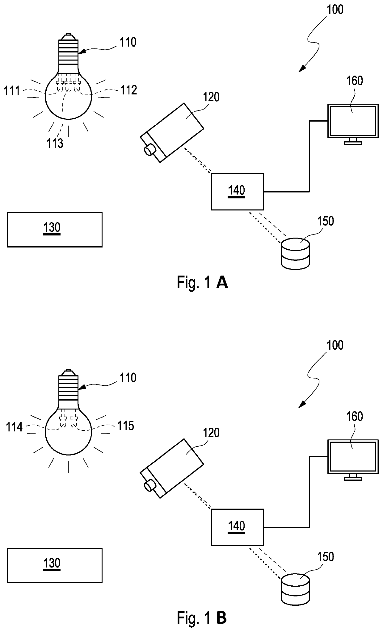
[0090]FIG. 1A and FIG. 1B show schematically embodiments of the proposed system 100. The system 100 includes at least one object 130 to be recognized. Further the system 100 includes a sensor 120 which can be realized by an imager, such as a camera, particularly a multispectral or a hyperspectral camera. The system 100 further includes a light source 110. The light source 110 is composed of different individual illuminants, the number of which and nature thereof depend on the method used. For example 1 as indicated in FIG. 1A, three illuminants are provided and the three illuminants are commonly available incandescent 111, compact fluorescent 112, and white light LED 113 bulbs. The light source may also be composed of two illuminants as shown in FIG. 1B. For example 2, only two illuminants are provided, the two illuminants are custom LED illuminants 114 and 115. Illuminant 114 consists of three LEDs operating at 5 V. One LED is a 400 nm LED from VCC (VAOL-5GUV0T4), with an inline re...


PUM


Abstract

A method and system for object recognition via a computer vision application including an object to be recognized, the object having an object specific luminescence spectral pattern, a light source including at least two illuminants for illuminating a scene including the object to be recognized by switching between the two illuminants, a sensor configured to capture radiance data of the scene including the object when the scene is illuminated by the light source, and a data storage unit storing fluorescence spectral patterns together with appropriately assigned respective objects. The method and system further include a data processing unit configured to extract the object specific fluorescence spectral pattern from the radiance data of the scene and to match the extracted object specific fluorescence spectral pattern with the fluorescence spectral patterns stored in the data storage unit, and to identify a best matching fluorescence spectral pattern and its assigned object.

Description

[0001]The present invention refers to a method and a system for object recognition via a computer vision application.[0002]Computer vision is a field in rapid development due to abundant use of electronic devices capable of collecting information about their surroundings via sensors such as cameras, distance sensors such as LIDAR or radar, and depth camera systems based on structured light or stereo vision to name a few. These electronic devices provide raw image data to be processed by a computer processing unit and consequently develop an understanding of an environment or a scene using artificial intelligence and / or computer assistance algorithms. There are multiple ways how this understanding of the environment can be developed. In general, 2D or 3D images and / or maps are formed, and these images and / or maps are analyzed for developing an understanding of the scene and the objects in that scene. One prospect for improving computer vision is to measure the components of the chemi...

Claims


Application Information

Patent Timeline
Patent Type & Authority Applications(United States)
IPC IPC(8): G06T7/521G06T7/73G06V10/141G06V10/147G06V10/22
CPCG06T7/521G06T7/73G01N21/88G06V10/141G06V10/147G06V10/22G06V10/255G06T2207/10152
Inventor KURTOGLU, YUNUS EMRECHILDERS, MATTHEW IAN
Owner BASF COATINGS GMBH
Why Eureka
Try Eureka