Method and apparatus for recognition of color brightness variations

a color brightness and variation technology, applied in the direction of material analysis, lighting and heating apparatus, instruments, etc., can solve the problems of vehicle bodies with foggy and mottled paint coats that cannot be detected, parameter deviations at certain light conditions prove to be serious defects,

Inactive Publication Date: 2006-04-04
DR ING H C F PORSCHE AG
View PDF21 Cites 0 Cited by
  • Summary
  • Abstract
  • Description
  • Claims
  • Application Information

AI Technical Summary

Benefits of technology

[0004]It is an object of the invention to provide an improved method and a system for visually detecting ...

Problems solved by technology

As a result of the insufficient layer thickness of the coloring paint (base paint), fogginess and mottling will then be visible mainly on the sides of the vehicle body.
In normally illuminated factory hangars, paint shop lines and even at well illuminated test sites, vehicle bodies with foggy and mottled paint coats can ...

Method used


Image

  • Method and apparatus for recognition of color brightness variations
  • Method and apparatus for recognition of color brightness variations
  • Method and apparatus for recognition of color brightness variations

Examples


Embodiment Construction

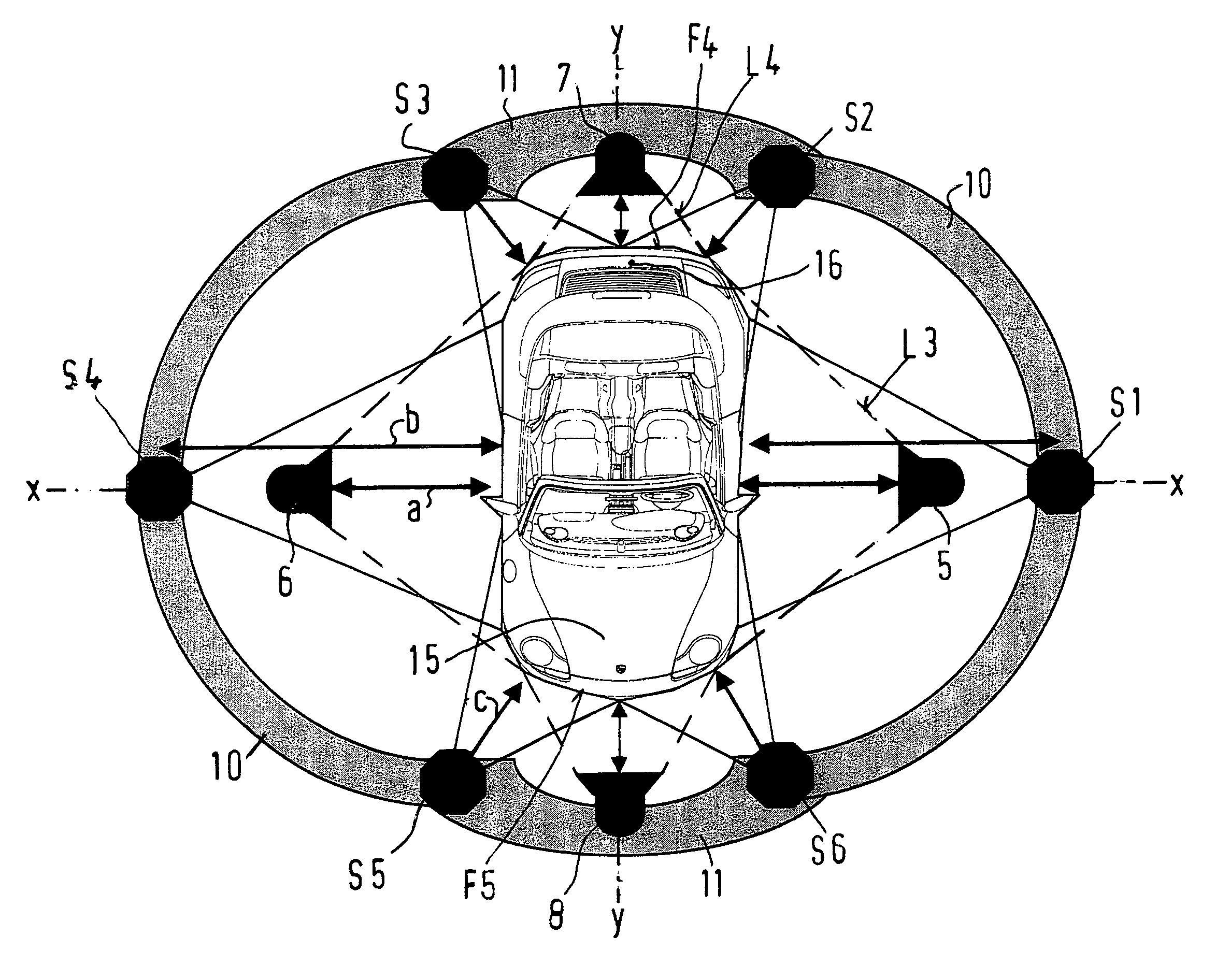
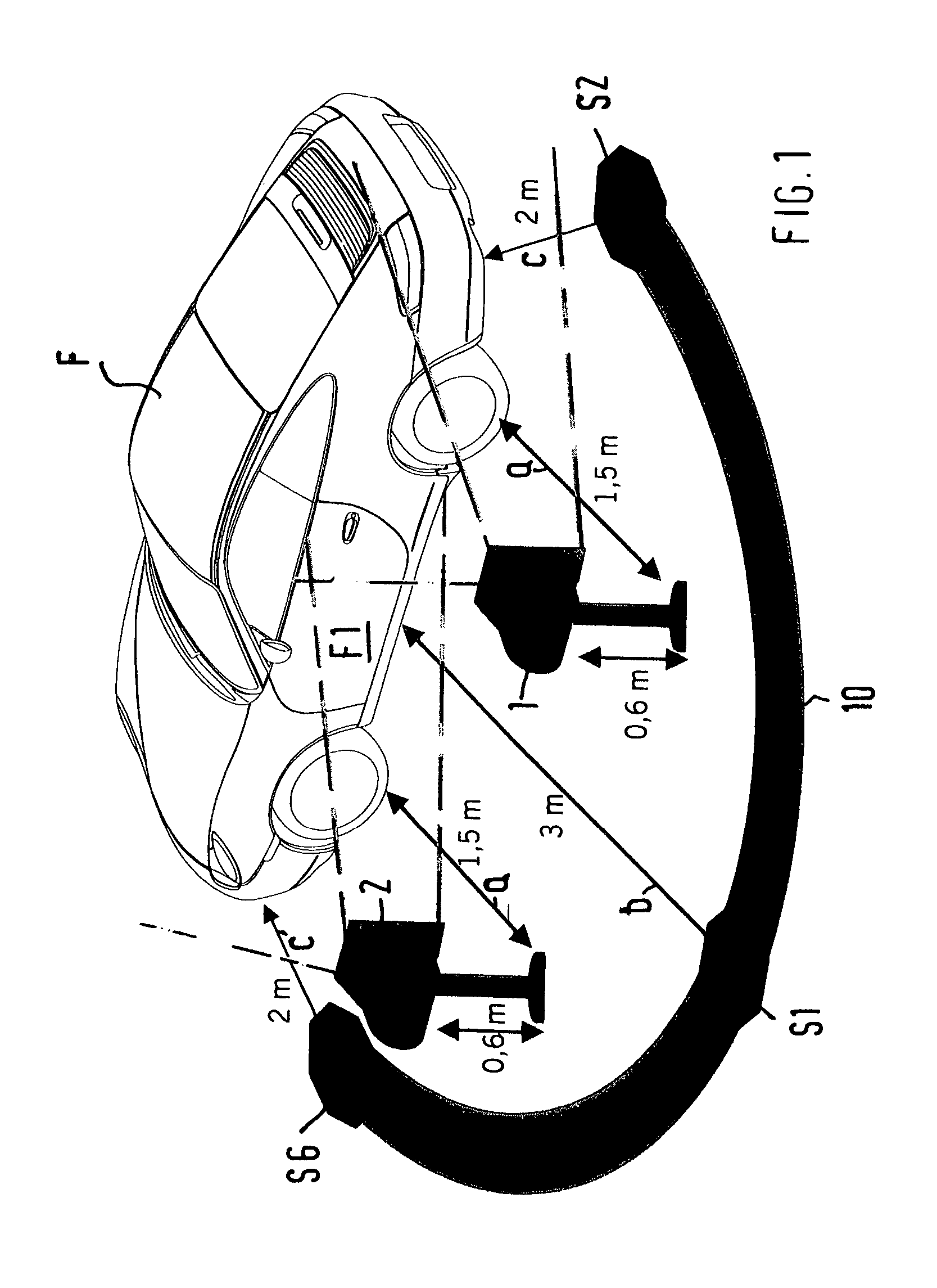
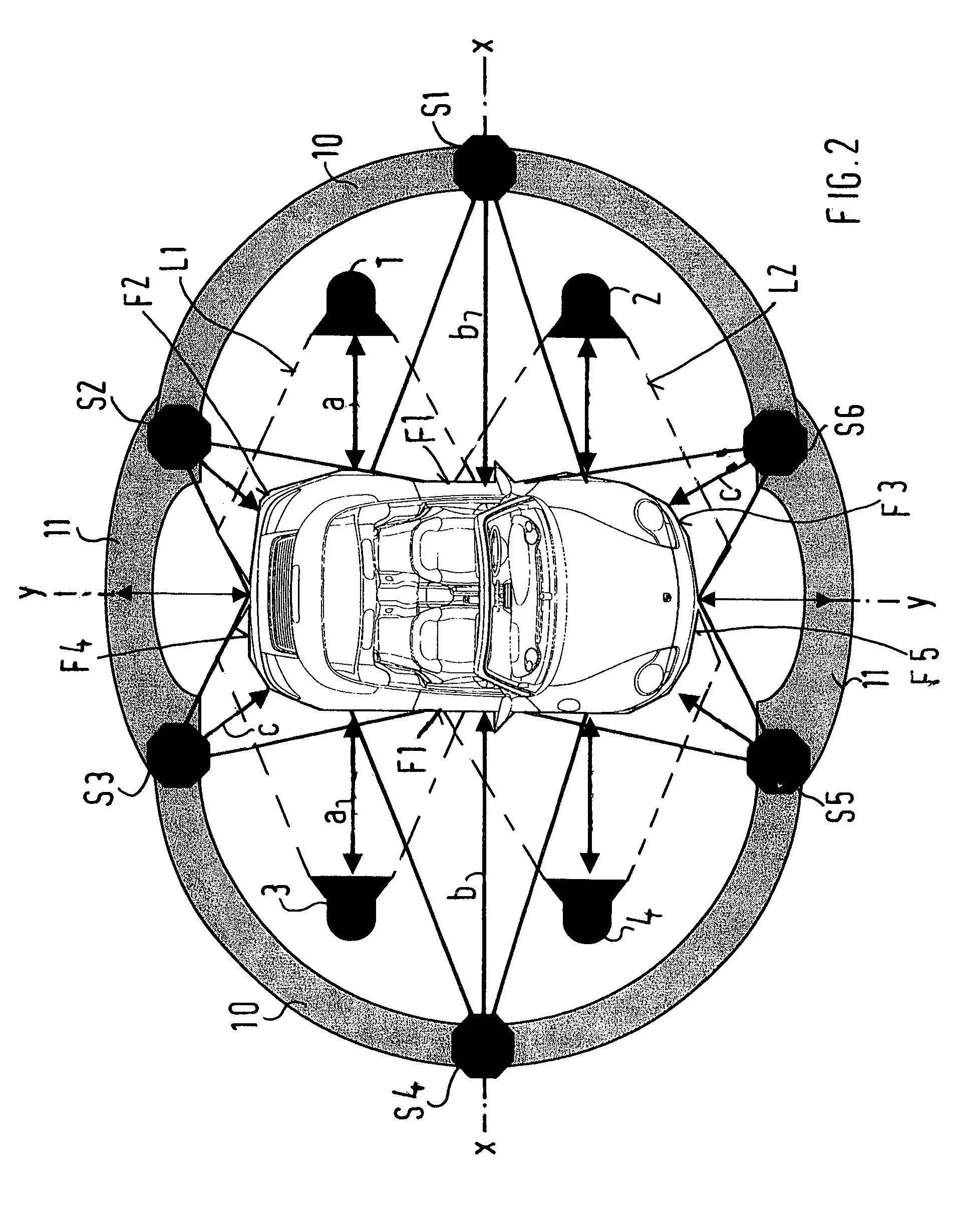
[0033]Fixedly positioned light beaming devices 1, 2, 3 and 4 according to FIGS. 1 and 2 and fixedly positioned light beaming devices 5, 6, 7 and 8 according to FIG. 3 are provided for judging the paint surfaces on vehicle bodies. These light beaming devices are arranged within a marked path 10, 11, different viewing positions S1 to S6 for an observer being arranged on this path 10, 11.

[0034]As illustrated in FIG. 1, the distances of the light beaming devices from the vehicle F are fixed at a distance a=1.5 m. The viewing positions S1 and S4 on the path 10 are fixed at a distance b=3 m from the vehicle F, the viewing positions S2, S3, S5 and S6 being provided at a distance c=2 m with respect to the vehicle.

[0035]The marked path 10, which is in each case arranged at a distance laterally of the vehicle F, is constructed as a semicircle and changes into another arc 11 in front of and behind the vehicle. According to FIG. 2, the viewing positions S1 and S4 are provided on these paths 10,...


PUM


Abstract

In the case of a method and a system for visually detecting paint gloss deviations, particularly a fogginess and mottling of the paint, in a surface paint coat of a vehicle by means of an illuminating system illuminating the vehicle, the outer surfaces of the two vehicle sides as well as additional surfaces of the forward and rearward vehicle body are illuminated by light beaming devices of the illuminating system in a partially areal manner. These surfaces are to be checked at a distance from the vehicle at predefined viewing ranges and from fixed viewing positions on a marked path.

Description

BACKGROUND AND SUMMARY OF THE INVENTION[0001]This application claims the priority of Germany, filed Sep. 13, 2002, the disclosure of which is expressly incorporated by reference herein.[0002]The invention relates to a method and a system for visually detecting deviations in paint gloss according to the preamble of claim 1.[0003]From European Patent Document EP 0 286 994 A2, a method and a system are known for detecting surface defects, preferably for detecting paint defects on the surface of a motor vehicle body. By means of an illuminating system, a streak of light is generated on the surface, and this streak of light is guided by means of a relative movement between the illuminating system and the surface over this surface, and streak-shaped sections of the surface of the objects are in each case recorded in steps in the area of the light streak. Further, from International Patent Document WO 98 / 08078, a system for the visual inspection of the surface finish of matching surfaces i...

Claims


Application Information

Patent Timeline
IPC IPC(8): G01N21/55G01N21/88
CPCG01N21/57G01N21/8806G01N21/8803
Inventor RINGLER, RALFPAWLOWSKI, MARIO
Owner DR ING H C F PORSCHE AG
Why Eureka
Try Eureka