
Dental bite block

a technology of dental implants and bite blocks, applied in the field of dental implants, can solve the problems of unintended injury, and achieve the effects of preventing bite accidents, avoiding excessive contact or interference, and minimizing discomfort for children

Inactive Publication Date: 2020-09-10
STEPANEK CHRISTINE +1
View PDF0 Cites 0 Cited by
  • Summary
  • Abstract
  • Description
  • Claims
  • Application Information

AI Technical Summary

Benefits of technology

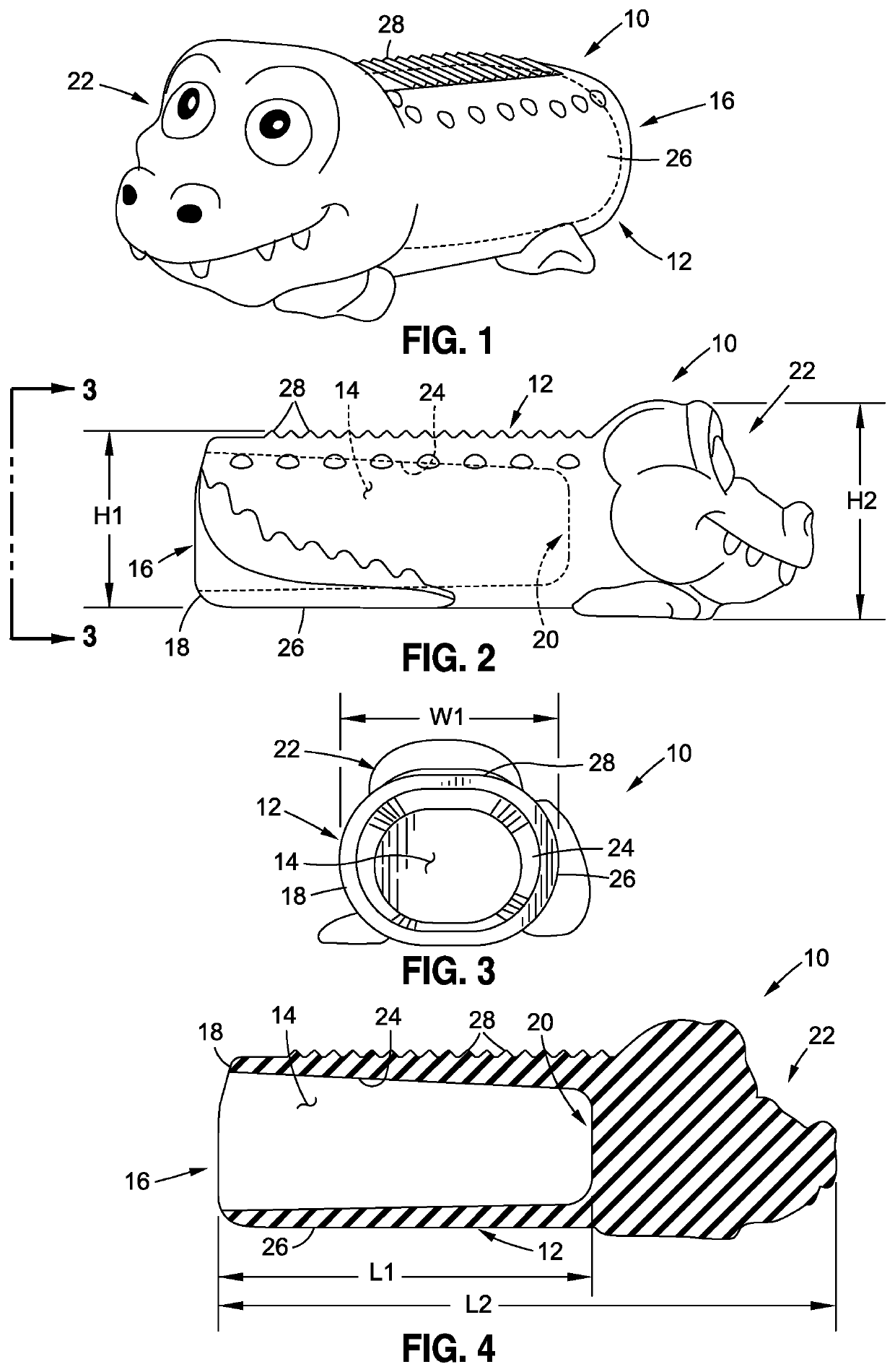
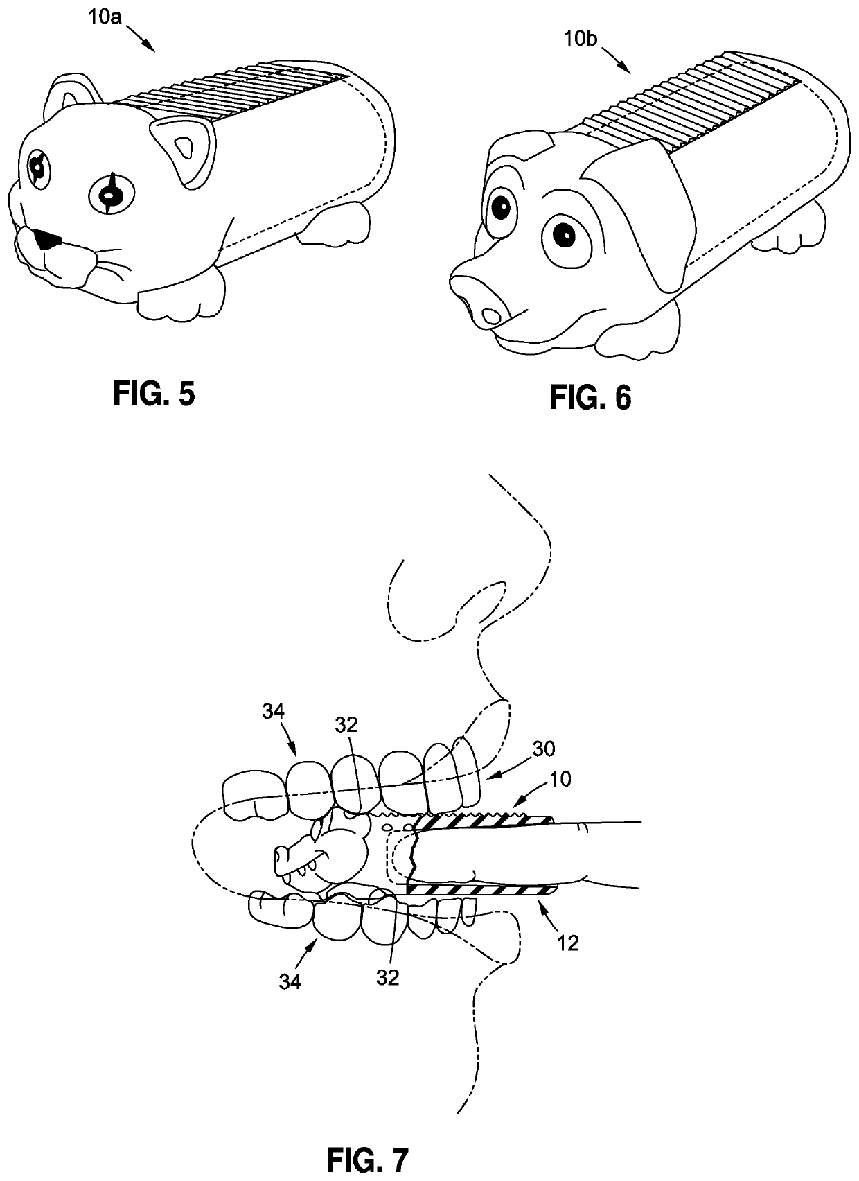
The patent describes a bite block that is designed to be placed in a young child's mouth to prevent biting accidents and facilitate dental inspection. The bite block has a unique external appearance that is shaped and sized to minimize discomfort for the child. It includes ridges or serrations to grip the child's teeth and hold the mouth open for inspection. It is made from a rubber material that is safe and easy to mold. The technical effects of this invention include improved safety and comfort for dental procedures in young children and individuals with special needs.

Problems solved by technology

With particular regard to young children, dental examinations or treatments administered by a dental professional, or even simple inspections of the mouth, teeth or gums by a parent or caregiver, are known to often present unique challenges.
As will be recognized, if that object happens to be the finger of a dental professional, parent or caregiver, injury can certainly occur as an unintended result.
Though this risk of injury may be mitigated by the initial advancement of a conventional bite block into the child's mouth, the size and shape of currently know bite blocks will typically do little if anything to curb the child's anxiety or potential discomfort which, as indicated above, often gives rise to the bite response in the first place.

Method used


Image

  • Dental bite block
  • Dental bite block

Examples


Embodiment Construction

[0019]Referring now to the drawings, wherein the showings are for purposes of illustrating a preferred embodiment of the present disclosure only, and are not for purposes of limiting the same, FIGS. 1-4 depict an exemplary bite block 10 constructed in accordance with such disclosure. The bite block 10 is essentially a hollow, tubular structure comprising an elongate, tubular main body portion 12. The main body portion 12 defines an interior chamber 14. The interior chamber 14 is accessible via an open first end 16 of the main body portion 12 which is defined by a distal rim 18 thereof. A second end 20 of the main body portion 12, which is disposed in opposed relation to the first end 16, is closed (or at least partially closed) as a result of the integral formation of the head portion 22 of the bite block 10 thereon. As will be discussed in more detail below, in the bite block 10, it is contemplated that at least the head portion 22 will be formed or molded to have aesthetic attribu...


PUM


Abstract

A bite block generally comprising a firm, hollow tube, the inner diameter of which is adapted to accommodate the finger (e.g., the index finger) of a dental professional (e.g., dentist, hygienist), healthcare worker, parent or caregiver. In one implementation, one of the opposed ends of the bite block is closed, with the opposite, remaining end being open as needed to accommodate the advancement of the finger into the interior of the bite block. The bite block is provided with exterior surface characterizations or aesthetic features / attributes which are indicative of a juvenile motif, and is further provided in a shape and with corresponding dimensions such that it is particularly suited for advancement into, and accommodation within, the interior of a young child's mouth in a manner which minimizes discomfort to the child.

Description

CROSS-REFERENCE TO RELATED APPLICATIONS[0001]Not ApplicableSTATEMENT RE: FEDERALLY SPONSORED RESEARCH / DEVELOPMENT[0002]Not ApplicableBACKGROUND1. Technical Field[0003]The present disclosure relates generally to dental appliances and, more particularly, to a mouth prop or bite block which is adapted to keep a patient's mouth open during a dental examination or procedure, is comfortable for the patient, and is uniquely shaped or otherwise provided with aesthetic attributes indicative of a juvenile motif intended to relax younger, juvenile patients in a manner which makes the dental examination or treatment experience less stressful while providing bite protection during the same.2. Description of the Related Art[0004]As is well known in the dental arts, dental mouth props, or bite blocks, are devices which are inserted into the patient's mouth between the upper and lower teeth to keep the mouth opened in a relatively fixed position. This allows access to the interior of the mouth for ...

Claims


Application Information

Patent Timeline
Patent Type & Authority Applications(United States)
IPC IPC(8): A61B90/16A61C5/90
CPCA61C5/90A61B90/16A61B1/24A61C2203/00
Inventor STEPANEK, CHRISTINESTEPANEK, MICHELLE
Owner STEPANEK CHRISTINE
Learn More