Gas turbine engine

a technology of gas turbine engine and combustion chamber, which is applied in the direction of continuous combustion chamber, combustion process, lighting and heating apparatus, etc., can solve the problems of reducing the durability of the contact face, affecting the performance of combustion, and affecting the ignitability of the combustion process, so as to reduce the bending moment and enhance the durability

Active Publication Date: 2020-09-10
HONDA MOTOR CO LTD
View PDF0 Cites 2 Cited by
  • Summary
  • Abstract
  • Description
  • Claims
  • Application Information

AI Technical Summary

Benefits of technology

[0008]The present invention has been accomplished in light of the above circumstances, and it is an object thereof to prevent the combustion performance of a reverse flow combustor from being

Problems solved by technology

However, since the air pressure is out of balance, being high to the rear of the reverse flow combustor and low in front thereof, there is the problem that the reverse flow combustor is urged forward in the axial direction due to the difference in pressure, the reverse flow combustor is deformed so as to change the mixing of fuel and air or the flow of gas within the combustor, and aspects of combustion performance such as ignitability, flame stability, and exhaust emissions will be degraded.
Since a nozzle guide vane guiding combustion gas generated in the reverse flow combustor to a turbine is urged rearward in the axial direction by means of the combustion gas flowing therein, there

Method used


Image

  • Gas turbine engine
  • Gas turbine engine
  • Gas turbine engine

Examples


first embodiment

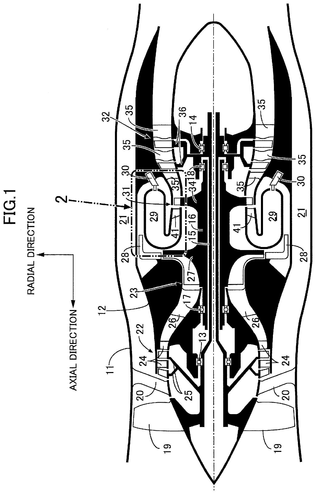
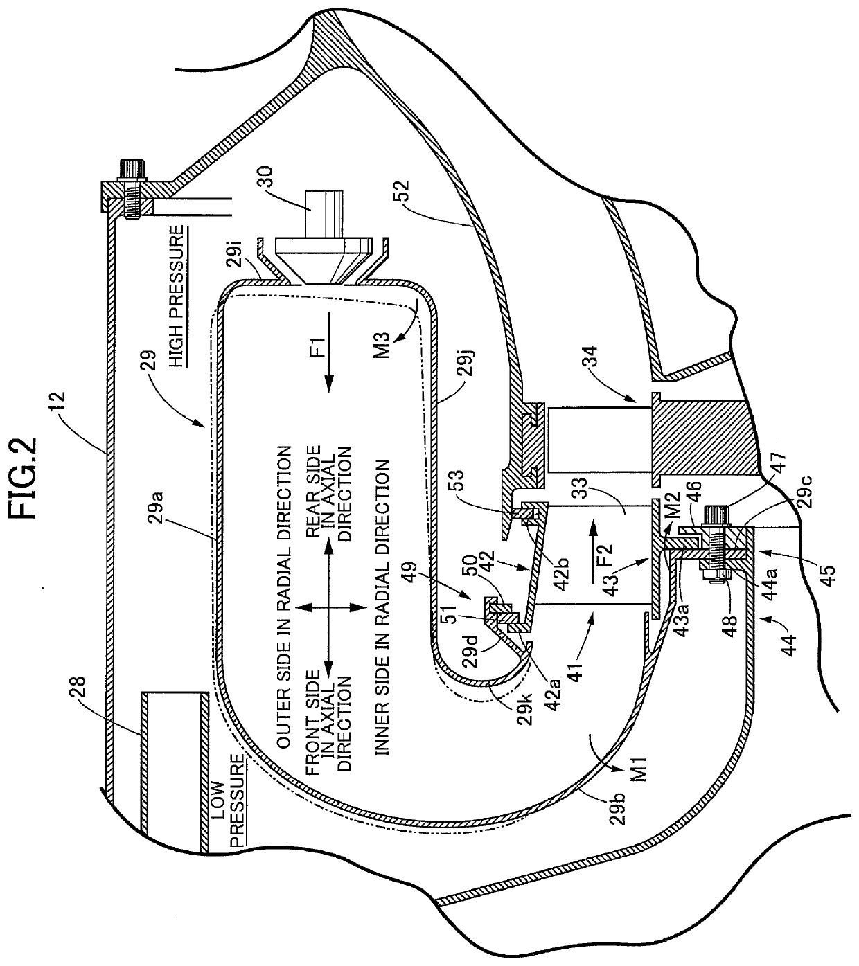
[0022]A first embodiment of the present invention is explained below by reference to FIG. 1 and FIG. 2. In the present specification, the axial direction is defined as a direction in which a low pressure system shaft 15 and a high pressure system shaft 16 of a gas turbine engine extend, and the radial direction is defined as a direction orthogonal to the axial direction.

[0023]As shown in FIG. 1, a gas turbine engine for an airplane to which the present invention is applied includes an outer casing 11 and an inner casing 12, a front part and a rear part of a low pressure system shaft 15 being rotatably supported in the interior of the inner casing 12 via a front first bearing 13 and a rear first bearing 14 respectively. A tubular high pressure system shaft 16 is relatively rotatably fitted around the outer periphery of an axially intermediate part of the low pressure system shaft 15, a front part of the high pressure system shaft 16 is rotatably supported on the inner casing 12 via a...

second embodiment

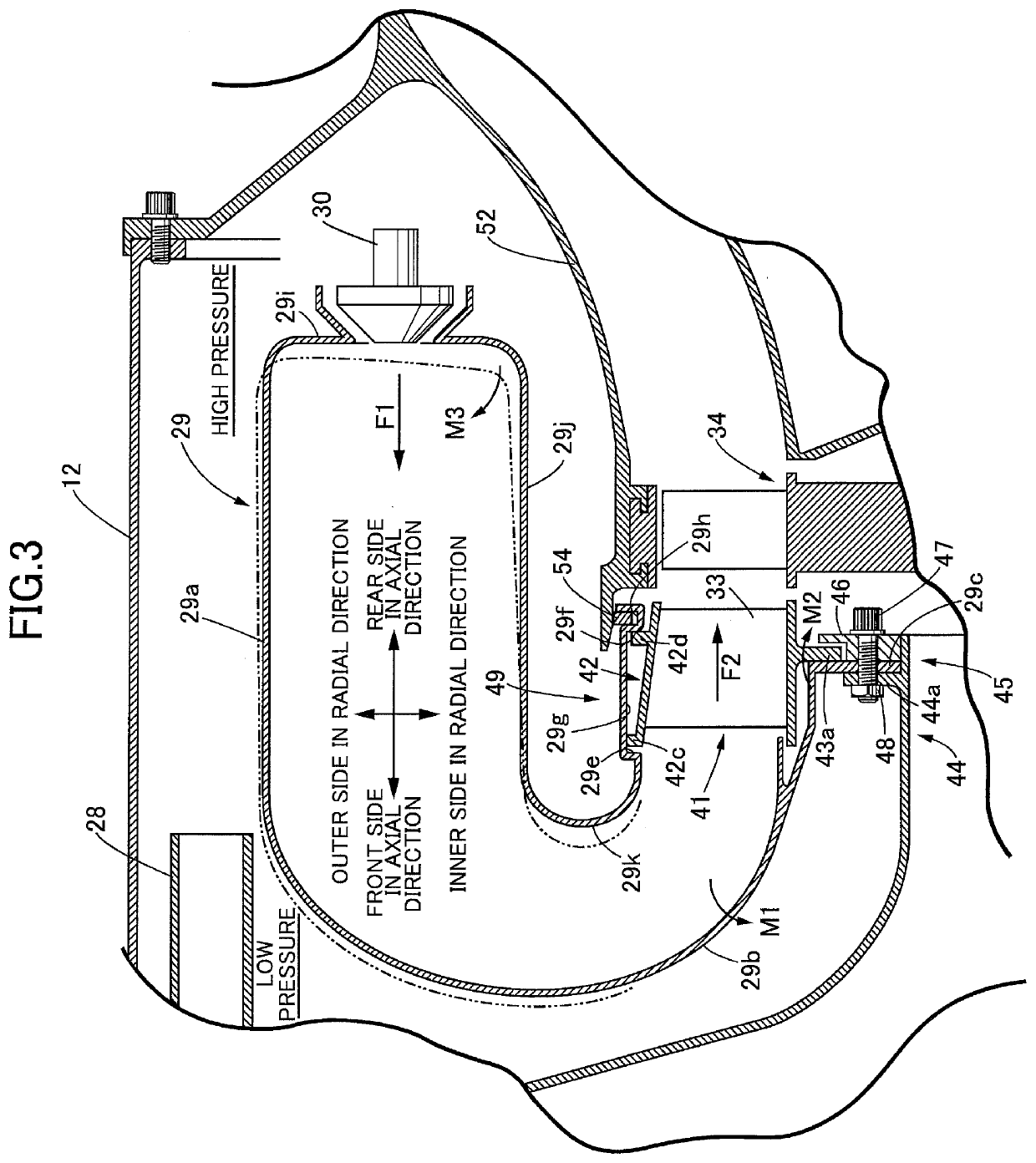
[0042]A second embodiment of the present invention is now explained by reference to FIG. 3.

[0043]The nozzle guide vane 41 of the first embodiment is formed from a single annular member or a plurality of annular members in which a plurality of fan-shaped segments are connected in the circumferential direction, but a nozzle guide vane 41 of the second embodiment is formed into an annular shape by connecting a plurality of fan-shaped segments in the circumferential direction. An engagement part 49 of the second embodiment is different from that of the first embodiment in terms of the structure. That is, formed on the radially outer side of the outside turn duct portion 29b of the reverse flow combustor 29 are the outside liner portion 29a, the dome portion 29i, the inside liner portion 29j, the inside turn duct portion 29k, and an annular recess portion 29g that is recessed radially outward via a first step portion 29e and a second step portion 29f, and formed to the rear of the annula...


PUM


Abstract

In a gas turbine engine, an inside turn duct portion and a nozzle guide vane are engaged together via an engagement part. An axially forward-facing load acting on a reverse flow combustor is transmitted to the vane via the engagement part. Therefore, it is possible to counteract an axially backward-facing load acting on the vane from combustion gas with the axially forward-facing load, thus reducing a bending moment acting on a support part of the vane and enhancing durability. Furthermore, part of the axially forward-facing load acting on the combustor acts on the support part via the vane. The axially forward-facing load acting on the support part of the combustor without via the vane is decreased by the above-mentioned part. Thus, it is possible to reduce bending moments acting on an outside turn duct portion and dome portion of the combustor and enhance durability, thereby preventing degradation of combustion performance.

Description

CROSS REFERENCE TO RELATED APPLICATIONS[0001]The present application claims priority under 35 U.S.C. § 119 to Japanese Patent Application No. 2019-41206 filed Mar. 7, 2019 the entire contents of which are hereby incorporated by reference.BACKGROUND OF THE INVENTIONField of the Invention[0002]The present invention relates to a gas turbine engine, in which a reverse flow combustor to which air compressed by a compressor is supplied comprises a dome portion, an outside liner portion, an inside liner portion, an outside turn duct portion, and an inside turn duct portion, a nozzle guide vane and the outside turn duct portion being supported on a stationary support body via a support part, and the nozzle guide vane guiding combustion gas generated in the reverse flow combustor to a turbine.Description of the Related Art[0003]Air compressed by a compressor is supplied to a space encircling a reverse flow combustor of such a gas turbine engine. However, since the air pressure is out of bala...

Claims


Application Information

Patent Timeline
IPC IPC(8): F23R3/54F23R3/60
CPCF23R3/54F23R3/60F23R2900/00017F23R2900/00005
Inventor KAMOI, YASUHARASAWAMURA, HIROSHI
Owner HONDA MOTOR CO LTD
Why Eureka
Try Eureka