
Connectors for respiratory assistance systems

a technology of respiratory assistance and connectors, applied in the field of respiratory assistance systems, can solve the problems of reducing the effectiveness of respiratory treatment, reducing patient comfort, and reducing patient comfort, so as to reduce the amount of condensate that drains toward the patient, reduce the effect of respiratory treatment, and reduce patient comfor

Pending Publication Date: 2020-09-17
FISHER & PAYKEL HEALTHCARE LTD
View PDF6 Cites 2 Cited by
  • Summary
  • Abstract
  • Description
  • Claims
  • Application Information

AI Technical Summary

Benefits of technology

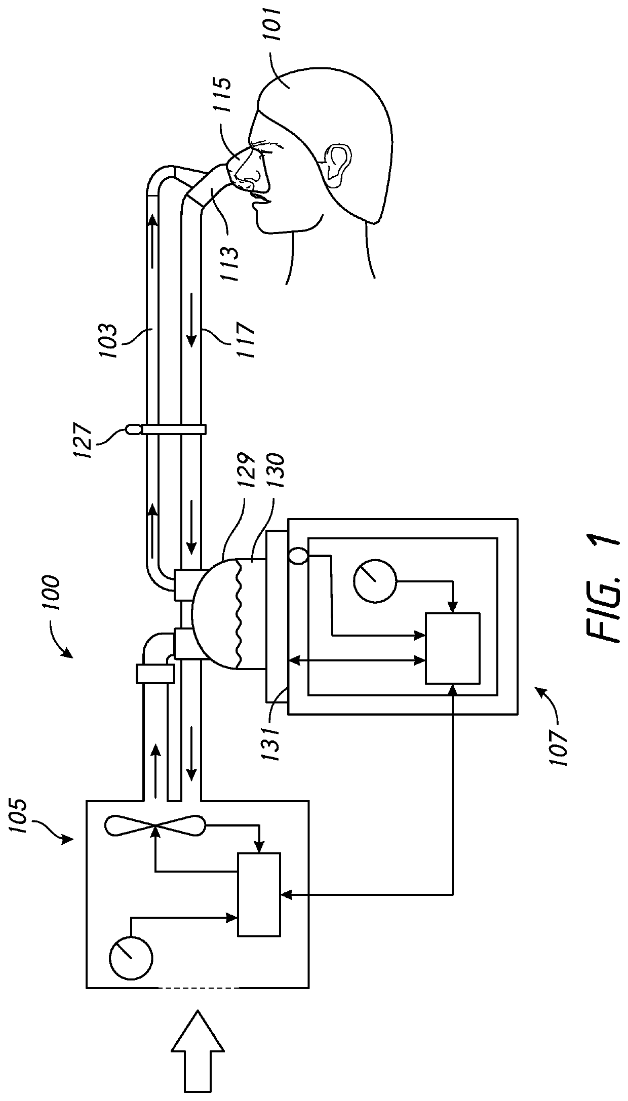
[0006]Condensate that forms in a respiratory assistance system may drain in one or more of three directions: toward the patient, into the inspiratory conduit toward the humidification device, and / or into the expiratory conduit toward the ventilator. Condensate that drains toward the patient may reduce effectiveness of respiratory treatment and / or decrease patient comfort. Thus, caregivers often may arrange the inspiratory conduit, the expiratory conduit, and / or the patient interface to reduce the amount of condensate that drains toward the patient. Condensate that drains toward the humidification device may cause at least partial occlusion of the inspiratory conduit which could reduce effective of respiratory treatment. Condensate that drains toward the ventilator may damage the ventilator.
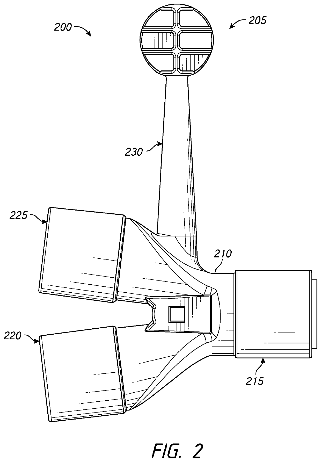
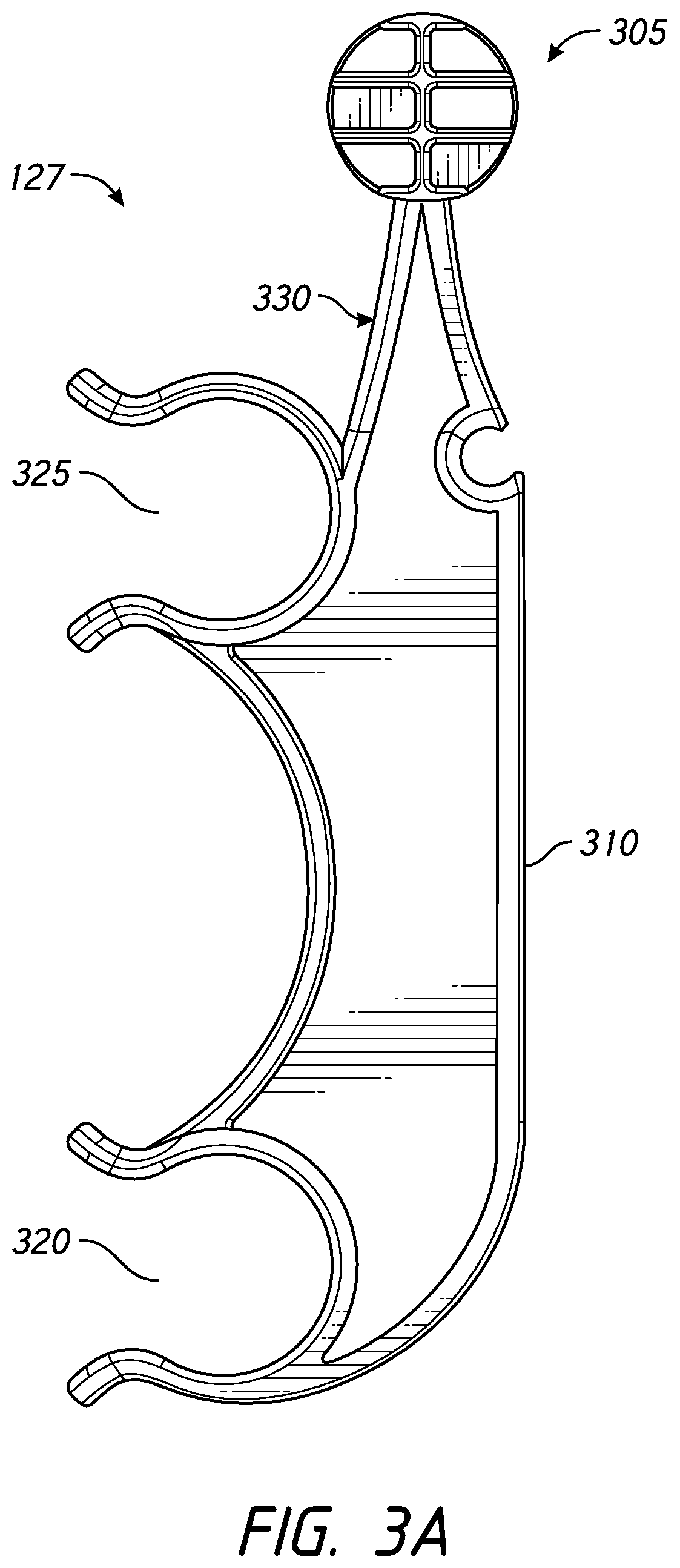
[0007]In a respiratory assistance system where the expiratory conduit includes features adapted to reduce condensate in gases delivered via the expiratory conduit to a gases source, it may be useful to decrease the proportion of condensate that drains toward the patient and / or into the inspiratory conduit by increasing the proportion of condensate that drains into the expiratory conduit. Embodiments are disclosed of connectors configured to at least decrease the proportion of condensate that drains into the inspiratory conduit by causing the portion of the wye-piece connected to the expiratory conduit to be positioned below the portion of the wye-piece connected to the inspiratory conduit. This arrangement allows condensate that reaches the wye-piece to naturally drain through gravitational force into the expiratory.
[0014]According to an another example embodiment, a connector comprises a coaxial wye-piece, the coaxial wye-piece comprising a body, the body comprising an inspiratory branch with an inspiratory conduit port, an expiratory branch with an expiratory conduit port, a patient end with a patient interface port, a fluid passageway between the inspiratory conduit port and the patient interface port, and a fluid passage between the expiratory conduit port and the patient interface port. The inspiratory branch may comprise a tip that extends into the fluid passageway between the expiratory conduit port and the patient interface port of the body. The tip of the inspiratory branch may comprise a lip, the lip configured to obstruct or impede a condensate from draining toward the inspiratory branch. An MDI or pressure port may also be located on the inspiratory branch at a location far enough away from the inspiratory conduit port so that the inspiratory conduit port may be connected to an inspiratory conduit. The patient end may have a gap in a wall between an inner surface and an outer surface, as well as a dual taper design that allows the patient end to act as a male or female connector. The gap may preserve the dual taper design while allowing less material to be used.

Problems solved by technology

Condensate that drains toward the patient may reduce effectiveness of respiratory treatment and / or decrease patient comfort.
Condensate that drains toward the humidification device may cause at least partial occlusion of the inspiratory conduit which could reduce effective of respiratory treatment.
Condensate that drains toward the ventilator may damage the ventilator.

Method used


Image

  • Connectors for respiratory assistance systems
  • Connectors for respiratory assistance systems
  • Connectors for respiratory assistance systems

Examples


Embodiment Construction

[0034]Terms

[0035]The term conduit refers to any tube, channel, or passageway that may be used in a respiratory assistance system. Conduits that may be used to carry respiratory gas in a respiratory assistance system include smooth-bore conduits, which may have inner wall surfaces that are smooth. The width of the conduit wall of a smooth-bore conduit may be constant. An example of a smooth-bore conduit is disclosed in International Application No. PCT / NZ2015 / 050028, which is herein incorporated by reference in its entirety. Conduits that may be used to carry respiratory gas in a respiratory assistance system may also include conduits with inner wall surfaces that are not smooth. Examples of such conduits include corrugated conduits. A corrugated conduit may have a series of parallel ridges or grooves. A corrugated conduit may also be known as a concertina or bellows conduit. Other types of conduits with inner wall surfaces that are not smooth may have helical or spiraling ridges or ...


PUM


Abstract

Connectors for respiratory assistance systems are disclosed that are configured to at least decrease the proportion of condensate that drains into an inspiratory conduit. The connectors include a setup that causes the portion of a wye-piece connected to an expiratory conduit to be positioned below the portion of the wye-piece connected to the inspiratory conduit. The connector can alternatively, or additionally, include a wye-piece that includes a ball attached to the wye-piece adjacent the inspiratory conduit port such that when the ball is connected to a medical stand, the expiratory conduit port is positioned below the inspiratory conduit port. The connector can alternatively or additionally include a circuit hanger that includes a cradles for both conduits and a ball attached to the circuit hanger adjacent the inspiratory conduit cradle such that when the ball is connected to a medical stand, the expiratory conduit cradle is positioned below the inspiratory conduit cradle. The connector can alternatively or additionally include a coaxial wye-piece that includes an inspiratory branch, an expiratory branch, and a patient end. The tip of the inspiratory branch that is internal to the coaxial wye-piece may have a lip and a narrowed diameter, features which obstruct or reduce condensate from entering the inspiratory branch and the inspiratory conduit regardless of the coaxial wye-piece orientation or position.

Description

INCORPORATION BY REFERENCE TO ANY PRIORITY APPLICATIONS[0001]This application is a continuation of U.S. patent application Ser. No. 15 / 511,093, filed Mar. 14, 2017, which is a U.S. National Phase of International Patent Application No. PCT / NZ2015 / 050151, filed Sep. 17, 2015, which claims the priority benefit of U.S. Provisional Application No. 62 / 051,860, filed Sep. 17, 2014, the entirety of which is hereby incorporated by reference herein. Any and all applications for which a foreign or domestic priority claim is identified in the Application Data Sheet as filed with the present application are hereby incorporated by reference under 37 CFR 1.57.BACKGROUNDTechnical Field[0002]The present disclosure generally relates to respiratory assistance systems. More particularly, the present disclosure relates to conduit connectors for respiratory assistance systems.Description of the Related Art[0003]A respiratory assistance system may be used to provide respiratory gases to a patient from a ...

Claims


Application Information

Patent Timeline
Patent Type & Authority Applications(United States)
IPC IPC(8): A61M16/08A61M15/00A61M16/16A61M16/10A61M16/00
CPCA61M16/0069A61M15/009A61M16/109A61M2205/3368A61M2205/3653A61M16/0875A61M2209/082A61M16/16A61M16/1095A61M16/0833A61M16/0808A61M16/0841A61M16/08A61M2209/084
Inventor KEMPS, DAVID ROBERTHENSMAN, SALLY MARGARETPOWELL, KEVIN BLAKEFYFE, KATIE
Owner FISHER & PAYKEL HEALTHCARE LTD
Learn More