Lower thread supply device of sewing machine

a technology of sewing machine and lower thread, which is applied in the direction of tensioning devices, sewing apparatus, textiles and paper, etc., can solve the problems of difficult reproducing the adjustment of the tension of the lower thread of the sewing machine, and difficult quantitative adjustmen

Active Publication Date: 2020-09-17
JUKI CORP
View PDF0 Cites 0 Cited by
  • Summary
  • Abstract
  • Description
  • Claims
  • Application Information

AI Technical Summary

Problems solved by technology

For the change of the screw-in amount of the tension adjustment screw, quantitative adjustment is difficult.
As a result, it may be difficult to reproduce the adjustment of the tension of the lower thread of a sewing machine is difficult.

Method used


Image

  • Lower thread supply device of sewing machine
  • Lower thread supply device of sewing machine
  • Lower thread supply device of sewing machine

Examples


first embodiment

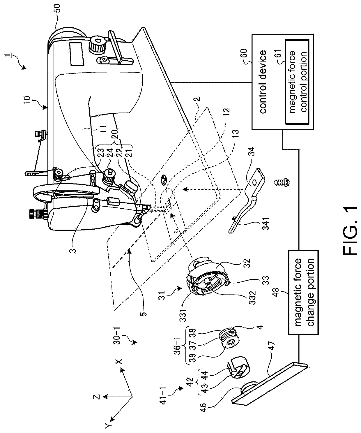
[0023]FIG. 1 is an exploded perspective view schematically showing an example of a lower thread supply device of a sewing machine 30-1 according to a first embodiment. In the following, first, a sewing machine 1 including the lower thread supply device of a sewing machine 30-1 according to the first embodiment is described specifically using FIG. 1. In the embodiment, position relationships between each portion are described based on a local coordinate system defined by the sewing machine 1. The local coordinate system is defined by an XYZ orthogonal coordinate system as shown in FIG. 1. A direction parallel to an X-axis in a predetermined surface is an X-axis direction. A direction parallel to a Y-axis in the predetermined surface and orthogonal to the X-axis is a Y-axis direction. A direction parallel to a Z-axis orthogonal to the predetermined surface is a Z-axis direction. In addition, in the embodiment, a plane including the X-axis and the Y-axis is appropriately referred to as...

second embodiment

[0076]A second embodiment is described. In the description below, structural components the same as that in the above embodiment are denoted by the same symbols, and description thereof is simplified or omitted.

[0077]

[0078]FIG. 7 is a perspective view showing an example of a bobbin case 41-2 in a lower thread supply device of a sewing machine 30-2 according to the second embodiment. FIG. 8 is a schematic diagram showing an example of a bobbin 36-2, the bobbin case 41-2 and a magnetic force member 46 according to the second embodiment. FIG. 7 is a view of the bobbin case 41-2 taken substantially from the shuttle side (the shuttle shaft side). FIG. 8 is a cross-section view similar to (A) and (B) of FIG. 4, (A) and (B) of FIG. 5 and FIG. 6 and a cross-section view in the XY-plane.

[0079]The lower thread supply device of a sewing machine 30-2 according to the second embodiment is obtained by changing the bobbin case 41-1 to the bobbin case 41-2 and changing the bobbin 36-1 to the bobbin...

third embodiment

[0093]A third embodiment is described. In the description below, structural components the same as that in the above embodiment are denoted by the same symbols, and description thereof is simplified or omitted.

[0094]

[0095]FIG. 9 is an exploded perspective view showing an example of a bobbin 36-3 and a bobbin case 41-3 in a lower thread supply device of a sewing machine 30-3 according to the third embodiment. FIG. 10 is a perspective view showing an example of the bobbin case 41-3 according to the third embodiment. FIG. 11 is a plan view showing an example of the bobbin case 41-3 according to the third embodiment. FIG. 12 is a schematic diagram showing an example of the bobbin 36-3, the bobbin case 41-3 and the magnetic force member 46 according to the third embodiment. FIG. 9 and FIG. 10 are both perspective views taken from the same direction. FIG. 11 is almost the same as FIG. 7 and is a view of the bobbin case 41-3 taken from the shuttle side (the shuttle shaft side). FIG. 12 is ...


PUM


Abstract

A lower thread supply device of a sewing machine includes a bobbin, a bobbin case, a magnetic force member, and a magnetic force change portion. The bobbin has a cylindrical portion for inserting into a spindle of a shuttle, a shuttle side flange portion, and a front surface side flange portion which is magnetic, and a lower thread is wound around an outer circumference of the cylindrical portion between the shuttle side flange portion and the front surface side flange portion. The bobbin case has a non-magnetic cover portion having a front surface side part and a side wall part, housing the bobbin and transmitting a magnetic force. The magnetic force member is arranged at the front surface side of the bobbin case and attracts the front surface side flange portion of the bobbin by a magnetic force via the bobbin case.

Description

CROSS-REFERENCE TO RELATED APPLICATION[0001]This application claims the priority benefit of Japan application no. 2019-049157, filed on Mar. 15, 2019. The entirety of the above-mentioned patent application is hereby incorporated by reference herein and made a part of this specification.BACKGROUNDTechnical Field[0002]The disclosure relates to a lower thread supply device of a sewing machine.Related Art[0003]Disclosed in patent literature 1 (Japanese Patent No. 4919332) is a technique in which tension of a lower thread of a sewing machine is changed by changing a screw-in amount of a tension adjustment screw arranged on a leaf spring arranged on an outer circumference of a bobbin case.[0004]For the change of the screw-in amount of the tension adjustment screw, quantitative adjustment is difficult. As a result, it may be difficult to reproduce the adjustment of the tension of the lower thread of a sewing machine is difficult.[0005]An aspect of the disclosure aims to facilitate the adju...

Claims


Application Information

Patent Timeline
Patent Type & Authority Applications(United States)
IPC IPC(8): D05B57/28D05B47/04D05B57/26D05B57/10
CPCD05B57/26D05B57/28D05B57/10D05B47/04D05B57/20D05B63/00
Inventor ASAMI, TAKESHIWAKATABE, JUNYADA, KAZUYUKI
Owner JUKI CORP
Why Eureka
Try Eureka