A Slide Valve for a Twin-Screw Compressor

Pending Publication Date: 2020-09-17
JOHNSON CONTROLS TYCO IP HLDG LLP
View PDF1 Cites 1 Cited by
  • Summary
  • Abstract
  • Description
  • Claims
  • Application Information

AI Technical Summary

Benefits of technology

[0018]On the basis of the structure of a prior slide valve, the slide valve's function of regulating a load of a twin-screw compressor is reserved for the slide valve of the present disclosure. In addition, a fluid pulsation attenuating structure is formed by providing cavities in the slide valve body that are configured to connect to an external fluid so that energy of air flow pulsations on the suction si

Problems solved by technology

As a result, the cooling medium fluid may flow unsteadily through the twin-screw compressor, which may cause air flow pulsations during suction and exhaust.
The air flow pulsations on the suction side and exhaust side of the twin-screw compressor may cause vibrations and noise during operation of the twin-screw compressor.
Currently, many technologies for governing exhaust puls

Method used


Image

  • A Slide Valve for a Twin-Screw Compressor
  • A Slide Valve for a Twin-Screw Compressor
  • A Slide Valve for a Twin-Screw Compressor

Examples


Example

[0031]The following will describe various specific implementation modes of the present disclosure by reference to the drawings which constitute a part of the present description. It should be understood that although the terms indicating directions, such as “before”, “behind”, “above”, “below”, “left”, and “right” are used in the present disclosure to describe various exemplified structural parts and components of the present disclosure, these terms are just used for the convenience of illustrations and are determined based on the exemplified directions in the drawings. Since the embodiments disclosed in the present disclosure can be set in different directions, these terms indicating directions are only used for illustrations, instead of restrictions. In the following drawings, the same components use the same reference numbers, and similar components use similar reference numbers so as to avoid repeated descriptions.

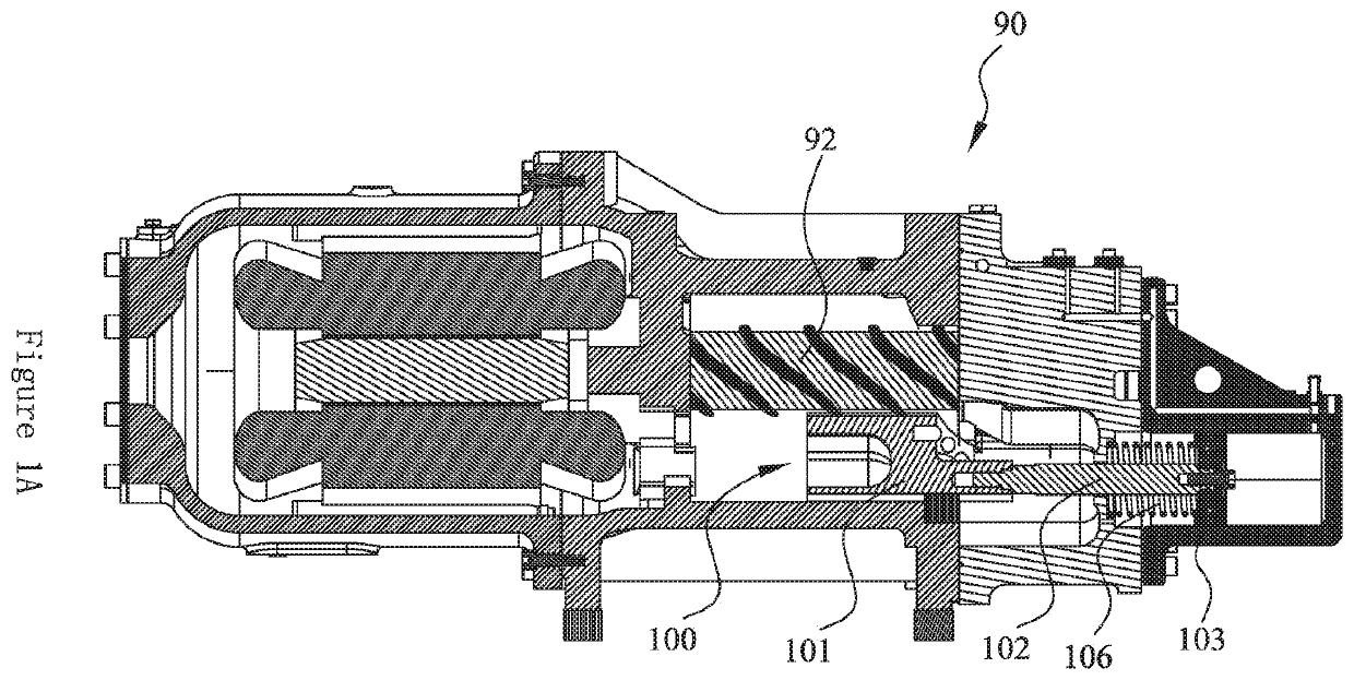
[0032]FIG. 1A is a cutaway view of a twin-screw compressor (90) i...


PUM


Abstract

The present application provides a slide valve, wherein the slide valve is configured to regulate a load of a twin-screw compressor. The slide valve comprises a slide valve body, wherein the slide valve body has a connecting end and a free end, the connecting end is configured to connect to a slide valve connecting rod of the twin-screw compressor, and the slide valve is driven to slide by the slide valve connecting rod. A cavity is formed in the free end of the slide valve body, and the slide valve has a passage configured to fluidly couple the cavity with an external fluid to reduce air flow pulsations on a suction side of the twin-screw compressor and thereby reduce overall air flow pulsations in the twin-screw compressor.

Description

TECHNICAL FIELD[0001]The present application relates to the field of compressors and, in particular, relates to a slide valve for a twin-screw compressor.BACKGROUND ART[0002]The slide valve is an important component which enables load regulation of the twin-screw compressor. By moving the position of the slide valve in an axial direction of a screw rotor of the twin-screw compressor, the effective working length of the screw rotor can be changed to regulate the amount of air delivered by the twin-screw compressor.[0003]Discontinuous inter-tooth volumes may be formed via the engagement of the screw rotor of the twin-screw compressor, which may cause the suction cavity and the exhaust cavity of the twin-screw compressor to be periodically connected to the working cavity of the twin-screw compressor. As a result, the cooling medium fluid may flow unsteadily through the twin-screw compressor, which may cause air flow pulsations during suction and exhaust. The air flow pulsations on the ...

Claims


Application Information

Patent Timeline
IPC IPC(8): F04C18/08F04C18/02F16K3/26
CPCF04C18/0238F04C18/088F16K3/26F04C28/12F04C29/0035F04C18/16F05B2210/12F04C2270/14
Inventor YANG, SHENGMEIMALIK, SHAHEBAZ
Owner JOHNSON CONTROLS TYCO IP HLDG LLP
Why Eureka
Try Eureka