Torque converter

a torque converter and converter technology, applied in the direction of rotary clutches, fluid couplings, gearings, etc., can solve the problem of reducing the size of the torque converter, and achieve the effect of reducing the size of the devi

Active Publication Date: 2020-09-17
EXEDY CORP
View PDF0 Cites 1 Cited by
  • Summary
  • Abstract
  • Description
  • Claims
  • Application Information

AI Technical Summary

Benefits of technology

The present invention aims to provide a compact torque converter with a lock-up device that uses a centrifugal clutch. The invention achieves this by incorporating a centrifugal element with a magnet and / or friction material on its outer surface. This allows for an increased clutch capacity and easy adjustment of friction force through the use of different friction materials. Additionally, the invention eliminates the need for a hydraulic pump to actuate the centrifugal clutch, making the device more compact.

Problems solved by technology

Therefore, this hinders compactness in size of the torque converter.

Method used


Image

  • Torque converter
  • Torque converter
  • Torque converter

Examples


Embodiment Construction

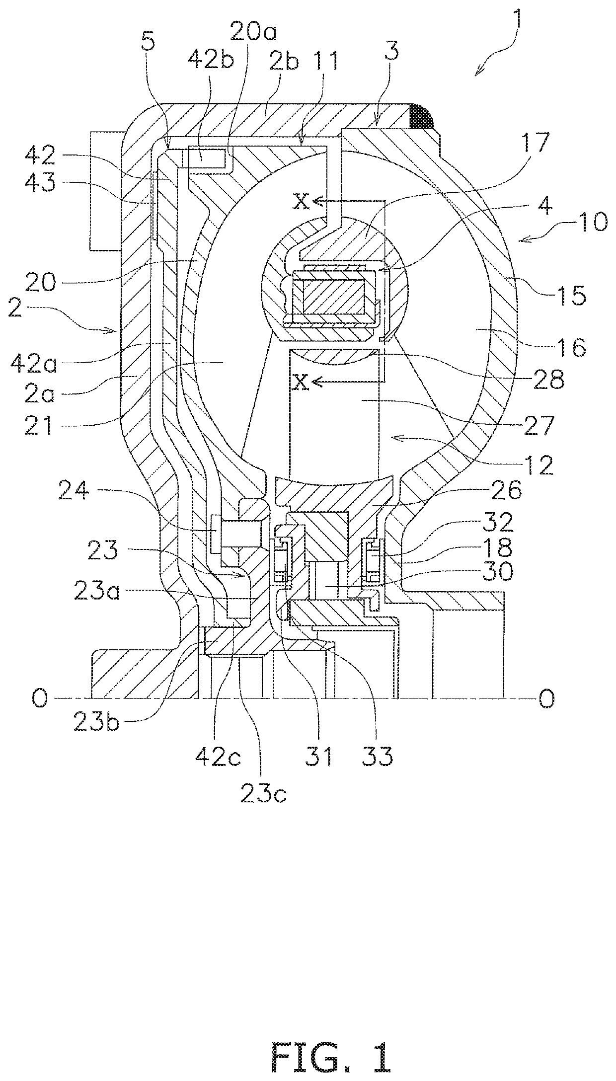
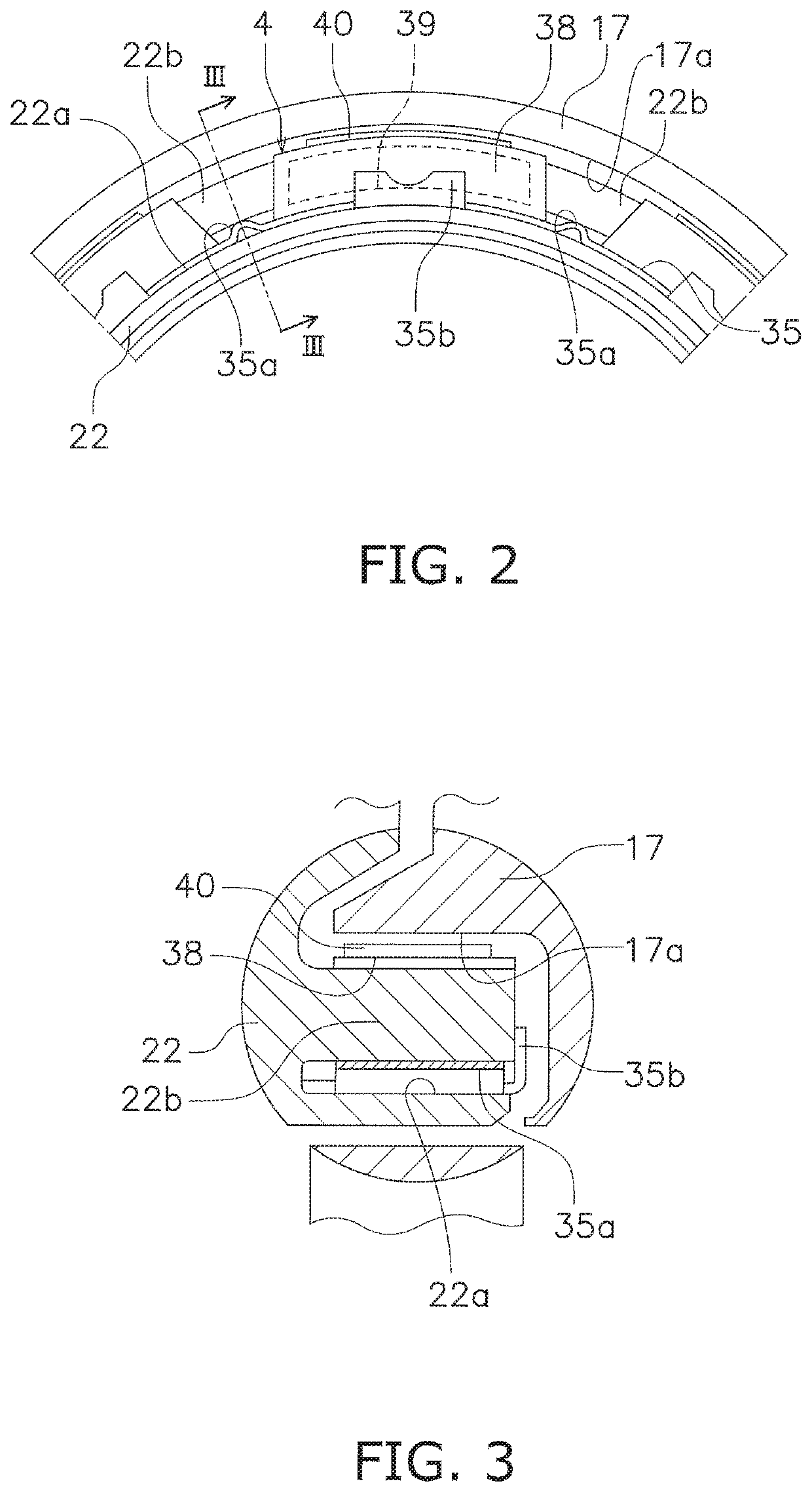
[0028]FIG. 1 is a partial cross-sectional view of a torque converter 1 according to a preferred embodiment of the present invention. On the other hand, FIG. 2 is a view of FIG. 1 as seen in a direction indicated by arrow X. In FIG. 1, an electric motor (not shown in the drawing) exemplified as a drive source is disposed on the left side, whereas a transmission (not shown in the drawing) is disposed on the right side. It should be noted that line O-O depicted in FIG. 1 is a rotational axis of the torque converter 1. It should be also noted that in the following explanation, the term “radial direction” is defined as a direction separating from the rotational axis, whereas the term “axial direction” is defined as a direction arranged along the rotational axis.

[Entire Configuration of Torque Converter 1]

[0029]The torque converter 1 is a device for transmitting a torque from the electric motor to an input shaft (not shown in the drawing) of the transmission. As shown in FIG. 1, the torqu...


PUM


Abstract

A torque converter includes a front cover to which a power is inputted, an impeller coupled to the front cover, a turbine from which the power is outputted, a stator and a centrifugal clutch. The impeller forms a hydraulic oil chamber together with the front cover. The impeller includes an impeller core. The turbine is opposed to the impeller. The turbine includes a turbine core. The stator is disposed between an inner peripheral part of the impeller and an inner peripheral part of the turbine. The stator is configured to regulate a hydraulic oil flowing from the turbine to the impeller. The centrifugal clutch is disposed in a space between the impeller core and the turbine core. The centrifugal clutch is configured to directly transmit the power from the impeller to the turbine when a rotational speed of the turbine is greater than or equal to a predetermined value.

Description

CROSS-REFERENCE TO RELATED APPLICATIONS[0001]This application claims priority to Japanese Patent Application No. 2019-043499, filed Mar. 11, 2019. The contents of that application are incorporated by reference herein in their entirety.TECHNICAL FIELD[0002]The present invention relates to a torque converter.BACKGROUND ART[0003]A torque converter is equipped with a lock-up device in order to reduce fuel consumption. The lock-up device is disposed between a front cover and a turbine and mechanically couples the front cover and the turbine in order to directly transmit a torque therebetween.[0004]A lock-up device described in Japan Laid-open Patent Application Publication No. S61-31731 has been proposed as this type of lock-up device. In this lock-up device, a clutch plate having a disc shape is provided between a front cover and a turbine, and a centrifugal clutch, including a ring member and a shoe assembly, is provided on an outer peripheral part of the clutch plate.[0005]On the othe...

Claims


Application Information

Patent Timeline
Patent Type & Authority Applications(United States)
IPC IPC(8): F16H45/02
CPCF16H2045/0263F16H45/02F16D27/14F16D43/18F16H2045/0278F16D33/18F16D41/00
Inventor MATSUOKA, YOSHIHIRO
Owner EXEDY CORP
Why Eureka
Try Eureka