
Torque limiter embedded damper device

Pending Publication Date: 2021-12-16
EXEDY CORP
View PDF2 Cites 0 Cited by
  • Summary
  • Abstract
  • Description
  • Claims
  • Application Information

AI Technical Summary

Benefits of technology

The present invention is for a device that includes a torque limiter and a damper that can be combined separately during assembly. This allows for a more compact device that is easier to install. Overall, this invention allows for a more efficient and compact torque limiter embedded damper device that can be assembled separately from each other.

Problems solved by technology

Hence, reduction in radial dimension of the device is made difficult.
However, in the damper device described in Japan Laid-open Patent Application Publication No. 2013-24364, due to a similar reason to the above, the torque limiter unit and the damper unit cannot be combined to each other after assembled separately from each other.

Method used


Image

  • Torque limiter embedded damper device
  • Torque limiter embedded damper device
  • Torque limiter embedded damper device

Examples


Embodiment Construction

[Entire Configuration]

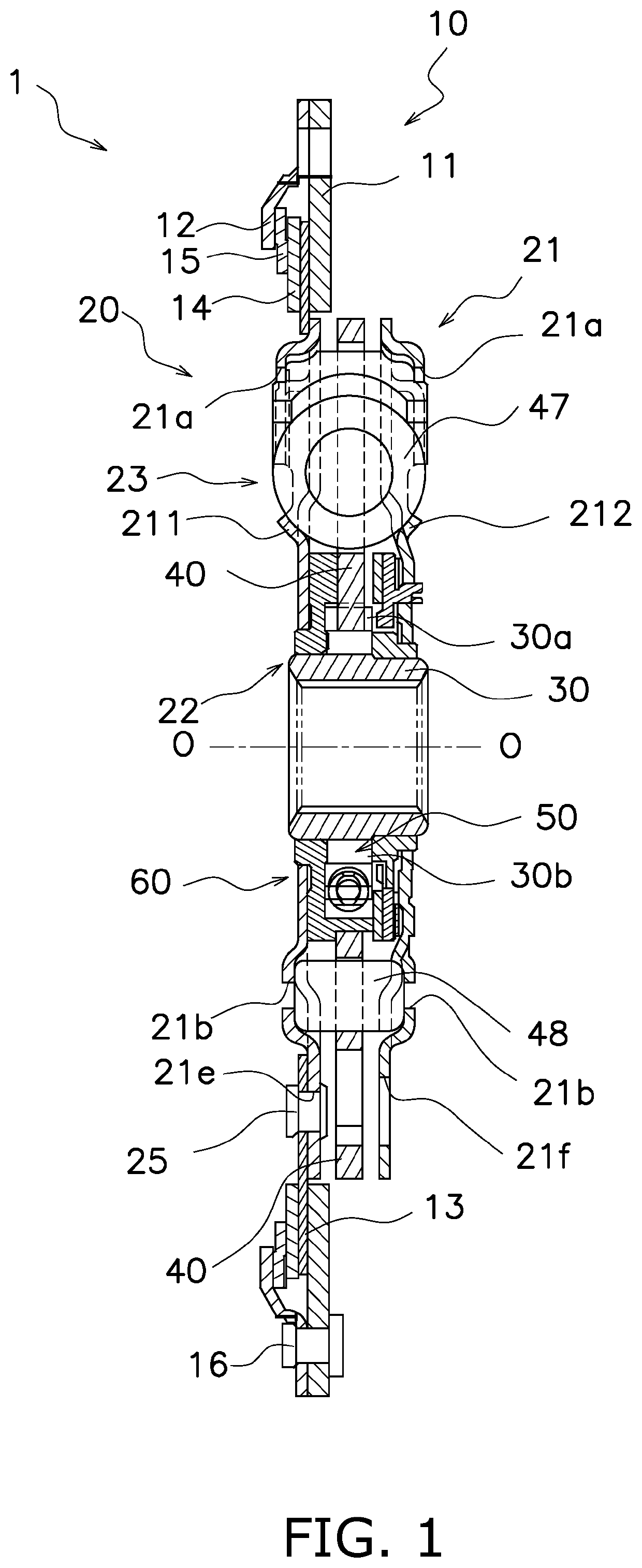
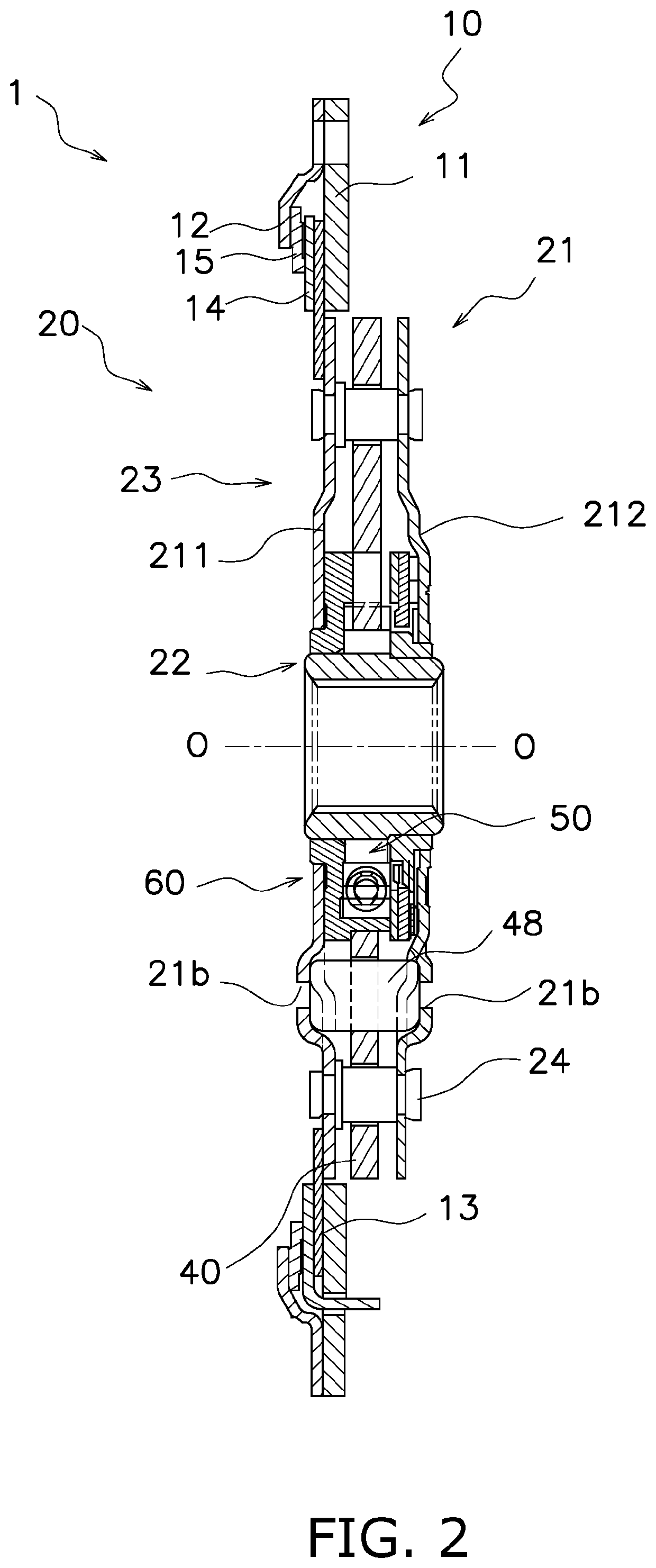
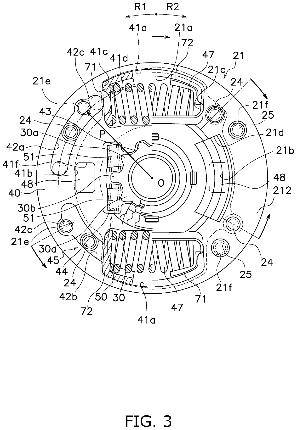
[0020]FIGS. 1 and 2 are cross-sectional views of a torque limiter embedded damper device 1 (hereinafter simply referred to as “damper device 1” on an as-needed basis) according to a preferred embodiment of the present invention. On the other hand, FIG. 3 is a front view of the damper device 1 in a condition that some constituent members are detached therefrom or are not illustrated in part. In FIGS. 1 and 2, line O-O indicates a rotational axis. In FIGS. 1 and 2, an engine is disposed on the left side of the damper device 1, whereas a drive unit, including an electric motor, a transmission, and so forth, is disposed on the right side of the damper device 1.

[0021]It should be noted that in the following explanation, the term “axial direction” refers to an extending direction of the rotational axis O of the damper device 1. On the other hand, the term “circumferential direction” refers to a circumferential direction of an imaginary circle about the rotational axi...


PUM


Abstract

A torque limiter embedded damper device includes a torque limiter unit and a damper unit. The damper unit includes a first rotor, a second rotor, and a stopper mechanism. The second rotor includes a flange axially opposed to the first rotor. The stopper mechanism restricts an angle of relative rotation between the first rotor and the second rotor to a predetermined angular range. The stopper mechanism includes a cutout and a stop pin. The cutout is provided in the flange of the second rotor. The stop pin is fixed to the first rotor. The torque limiter unit includes a friction plate having an annular shape. The annular friction plate is fixed at an inner peripheral part thereof to an outer peripheral part of first rotor or the second rotor by a fixation member. The fixation member is fastened in a state of penetrating the cutout of the flange.

Description

CROSS-REFERENCE TO RELATED APPLICATIONS[0001]This application claims priority to Japanese Patent Application No. 2020-103834, filed Jun. 16, 2020. The entire contents of that application are incorporated by reference herein in their entirety.TECHNICAL FIELD[0002]The present invention relates to a damper device, particularly to a torque limiter embedded damper device provided between a power source-side member and an output-side member.BACKGROUND ART[0003]A type of hybrid vehicle including an engine and an electric motor, for instance, uses such a torque limiter embedded damper device as described in Japan Laid-open Patent Application Publication No. 2013-24364 in order to prevent transmission of an excessive torque from an output side to an engine side in engine start and so forth.[0004]The torque limiter embedded damper device described in Japan Laid-open Patent Application Publication No. 2013-24364 is provided with a damper part, including a pair of plates and a plurality of tors...

Claims


Application Information

Patent Timeline
IPC IPC(8): F16D7/02F16D3/12F16F15/129F16F15/123
CPCF16D7/025F16D3/12F16F15/1292F16F2222/04F16F2232/02F16D2300/22F16F15/12353F16F15/1397F16F15/13461F16F15/1238F16F15/1297
Inventor UEHARA, HIROSHI
Owner EXEDY CORP
Learn More