Camera focus adjustment jig and camera focus adjustment method

Active Publication Date: 2020-09-24
HONDA MOTOR CO LTD
View PDF0 Cites 0 Cited by
  • Summary
  • Abstract
  • Description
  • Claims
  • Application Information

AI Technical Summary

Benefits of technology

The present invention provides a camera focus adjustment jig and method that can easily adjust the focus of a camera, without the need to separately position the movable arm and the inspection target at their respective different reference points. The adjusting unit can be positioned using the fixing part as the reference point, and the focus of the camera can be adjusted without moving the movable arm. This facilitates the camera focus adjustment and allows for appropriate adjustment of the view angles of multiple cameras simultaneously. The fixed reference point makes it unnecessary to move the movable arm and ensures quicker and easier camera focus adjustment, as compared to the related art.

Problems solved by technology

However, in the case in which the camera is fixed to a movable arm, it is necessary to not only move the movable arm to a position where the inspection target can be photographed with the camera based on a predetermined reference point of the movable arm, but also position the inspection target at a position where the inspection target can be photographed with the camera based on a predetermined reference point of the inspection target, and thereafter, the focus of the camera should be adjusted; therefore, such a case requires a tedious procedure.

Method used


Image

  • Camera focus adjustment jig and camera focus adjustment method
  • Camera focus adjustment jig and camera focus adjustment method
  • Camera focus adjustment jig and camera focus adjustment method

Examples


Embodiment Construction

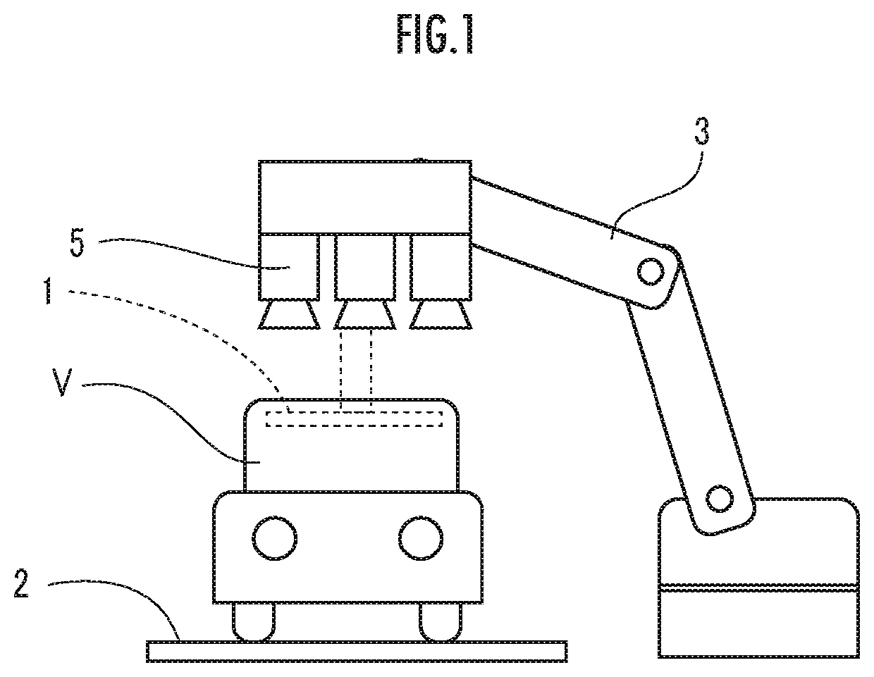
[0038]A camera focus adjustment jig according to an embodiment of the invention will be described with reference to the drawings. As shown in FIG. 1, the camera focus adjustment jig 1 of the present embodiment is used for an inspection device for inspecting defects of a coated film of an automobile V, and is a jig for adjusting focuses of three cameras 5 fixed to a fixing part 4 of a movable arm 3 such as a robot arm disposed on a manufacturing line 2 of the automobile V (which may also be a part of the automobile V). In the present embodiment, the inspection device is configured by the movable arm 3, the fixing part 4, the cameras 5, and illumination (not shown). For convenience of explanation, FIG. 1 shows the camera focus adjustment jig 1, but when the focus adjustment is actually performed with the camera focus adjustment jig 1 attached, the focus adjustment can be performed without moving the movable arm 3 to a photographing position shown in FIG. 1.

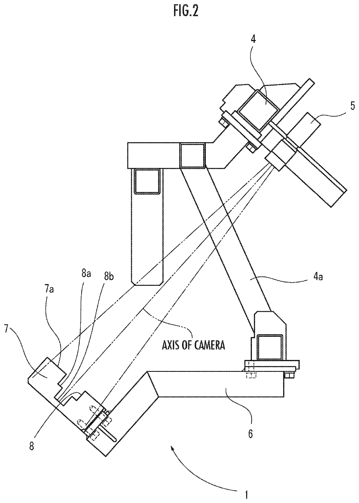
[0039]FIG. 2 shows the fixin...


PUM


Abstract

Provided is a camera focus adjustment jig (1) fixed to an inspection device and adjusting a focus of a camera (5), the inspection device including the camera (5) configured to photograph an automobile V, and a movable arm (3) to which the camera (5) is fixed via a fixing part (4) and configured to move the camera (5) to a photographing position where the automobile V is photographed. The camera focus adjustment jig (1) includes: a connection arm (6) connected to the fixing part (4); an adjusting unit (7) provided on the connection arm (6) and positioned, with respect to the camera (5), at a position equivalent to a position of the automobile V located at the photographing position; and display parts (9a, 9b) provided on a surface of the adjusting unit (7) facing the camera (5).

Description

BACKGROUND OF THE INVENTIONField of the Invention[0001]The present invention relates to a camera focus adjustment jig fixed to a movable arm provided in a manufacturing line or the like, and a camera focus adjustment method of the same.Description of the Related Art[0002]Conventionally, it is known that coating is applied to an automobile body to form a coated film thereon in a manufacturing process of the automobile body (see Japanese Patent Application Publication No. 2017-219478, for example).[0003]Coating defects may be caused in a coated film by bulges of approximately several tens of p,m, and its appearance may be impaired when the coating defects occurs. For this reason, after the coated film is formed, the coated film is photographed with a camera to inspect presence or absence of coating defects.SUMMARY OF THE INVENTION[0004]When determining presence or absence of coating defects through photographing with a camera, it is necessary to focus the camera on the inspection targ...

Claims


Application Information

Patent Timeline
IPC IPC(8): G03B13/32G03B17/56
CPCG03B17/561G03B13/32G03B43/00
Inventor ADACHI, MASAKAZUMATSUMOTO, JUNICHI
Owner HONDA MOTOR CO LTD
Why Eureka
Try Eureka