Stator and electric motor

a technology of electric motors and motors, applied in the direction of dynamo-electric components, dynamo-electric machines, magnetic circuit shapes/forms/construction, etc., can solve problems such as degrading the characteristics of electric motors

Active Publication Date: 2020-09-24
FANUC CORP
View PDF0 Cites 3 Cited by
  • Summary
  • Abstract
  • Description
  • Claims
  • Application Information

AI Technical Summary

Benefits of technology

[0005]However, in the above rotating electric machine, since the coils of each phase must be connected on one axial e

Problems solved by technology

As a result, torque ripple and unbalanced magnetic attraction are liable t

Method used


Image

  • Stator and electric motor
  • Stator and electric motor
  • Stator and electric motor

Examples


embodiment

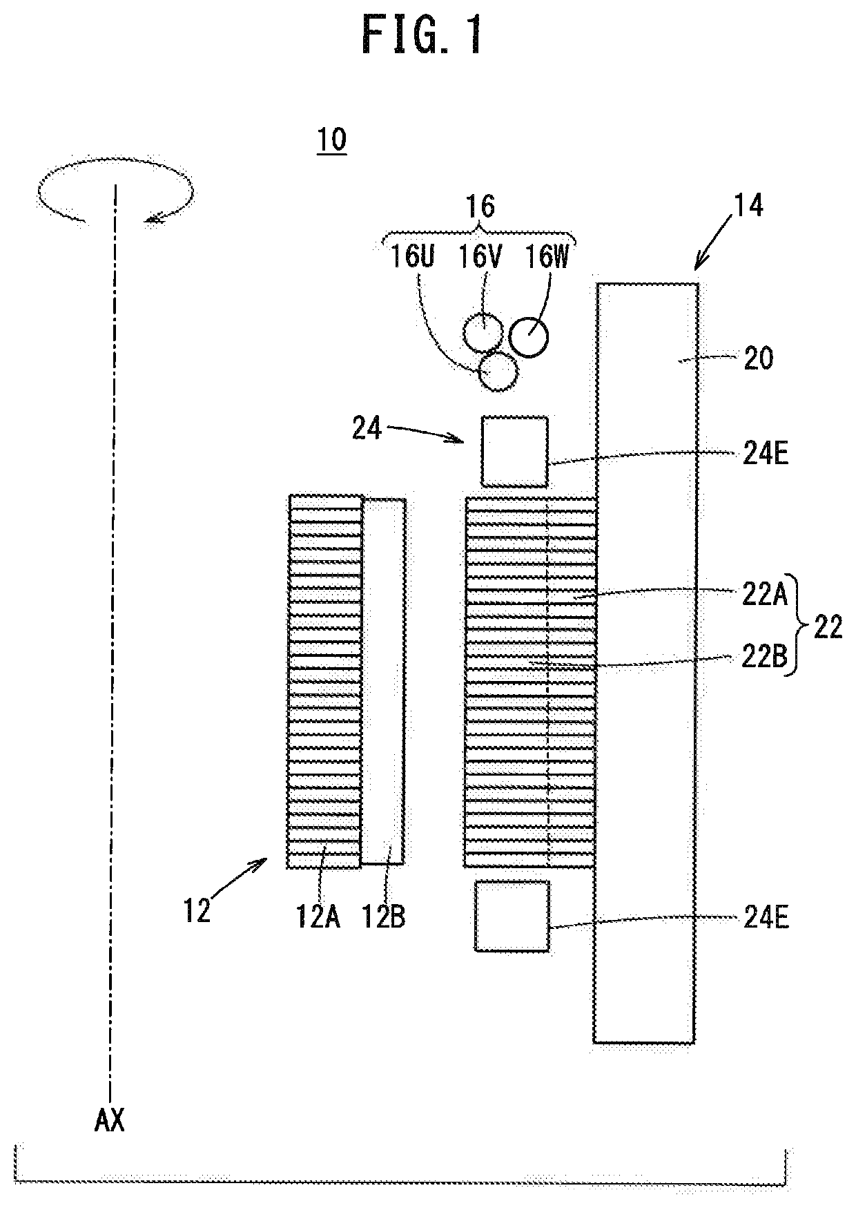
[0018]FIG. 1 is a schematic sectional view showing part of an electric motor 10. The electric motor 10 is, for example, an inner rotor type electric motor, and includes a rotor 12 having a rotor core 12A and magnets 12B, a stator 14 arranged outside the rotor 12, power lines 16 for supplying current to the stator 14, and an unillustrated neutral point.

[0019]The stator 14 includes a housing 20, a stator core 22, and coils 24. The housing 20 is a resin member for accommodating the stator core 22, the coils 24 and others, and is formed in a substantially cylindrical shape.

[0020]The stator core 22 is a member made of an iron-based metal disposed around a rotary axis AX of the electric motor 10, and is fixed to the housing 20. The stator core 22 has a core body 22A and a plurality of teeth 22B.

[0021]The core body 22A is formed in an annular shape, and the axis (center axis) of the annular-shaped core body 22A coincides with the rotary axis AX of the electric motor 10. The core body 22A m...


PUM


Abstract

A stator includes: a first wiring section connecting a coil wire end of a leading coil to a power line; and a second wiring section connecting a coil wire end of a last coil to a neutral point located on the power line side, by wiring that extends along a fewer-turns portion of the leading coil that has a smaller number of turns of wire than the last coil.

Description

CROSS-REFERENCE TO RELATED APPLICATION[0001]This application is based upon and claims the benefit of priority from Japanese Patent Application No. 2019-051388 filed on Mar. 19, 2019, the contents of which are incorporated herein by reference.BACKGROUND OF THE INVENTIONField of the Invention[0002]The present invention relates to a stator and an electric motor.Description of the Related Art[0003]There are three-phase motors known as electric motors. The three-phase motor includes U-phase, V-phase and W-phase coils provided on a stator core, and power lines for supplying current to the coils.[0004]Japanese Laid-Open Patent Publication No. 2016-039642 discloses a rotating electric machine in which the neutral point lead wire and the power-supply lead wire of each of three-phase coils wound on the teeth are extracted on one end side of the stator core in the axial direction and the extracted wires are connected to a neutral point connection part and a three-phase power supply part locate...

Claims


Application Information

Patent Timeline
IPC IPC(8): H02K1/16H02K3/52H02K3/28H02K1/14H02K3/12
CPCH02K1/165H02K3/522H02K3/12H02K1/146H02K3/28
Inventor SENOO, TATSUYA
Owner FANUC CORP
Why Eureka
Try Eureka