Fuel pump of compact structure for use in high torque

A fuel pump and fuel technology, applied in the directions of liquid fuel feeder, magnetic circuit shape/pattern/structure, winding conductor shape/pattern/structure, etc., can solve problems such as torque reduction, magnetic flux reduction, etc. The effect of corrosion, reducing inductance, and reducing the number of turns

Inactive Publication Date: 2008-03-05
DENSO CORP
View PDF6 Cites 0 Cited by
  • Summary
  • Abstract
  • Description
  • Claims
  • Application Information

AI Technical Summary

Problems solved by technology

However, if the axial length of the fuel pump is shortened without increasing the diameter of the fuel pump, the magnetic flux through the coil core is reduced
In this case, the generated torque is reduced

Method used


Image

  • Fuel pump of compact structure for use in high torque
  • Fuel pump of compact structure for use in high torque
  • Fuel pump of compact structure for use in high torque

Examples


no. 1 example

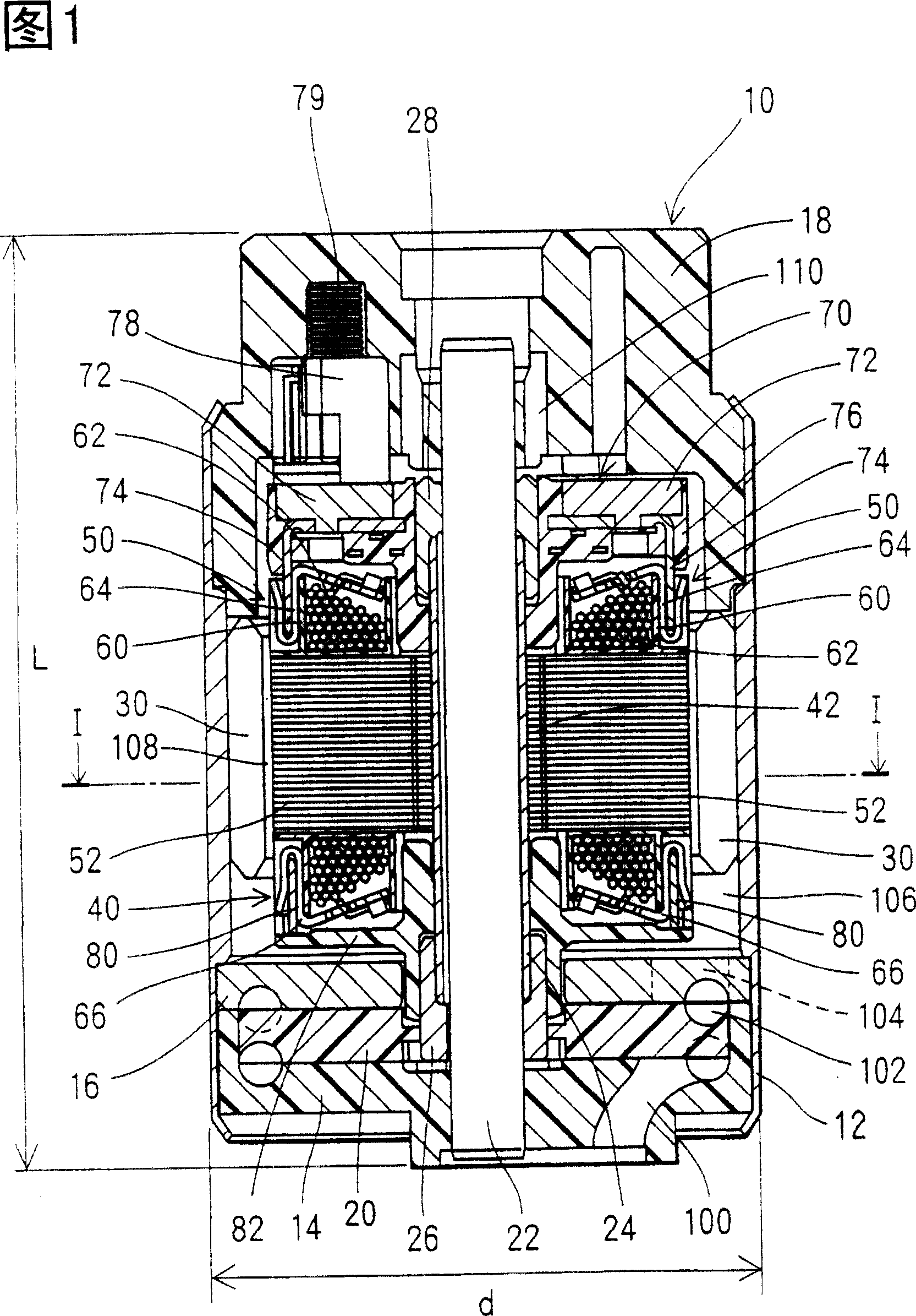
[0032] The fuel pump 10 shown in FIG. 1 is a tank pump. The fuel tank pump is installed, for example, in a fuel tank of a vehicle. A forged end cap 14 on the suction side and a forged end cap 18 on the discharge side are fixed in the housing 12 .

[0033] A pump cover 16 is supported by the suction side cover 14 and the housing 12 . A C-shaped pump passage 102 is formed between the suction side end cover 14 and the pump cover 16 . The suction side cover 14 and the pump cover 16 support an impeller 20 which is used as a rotating means for generating suction force.

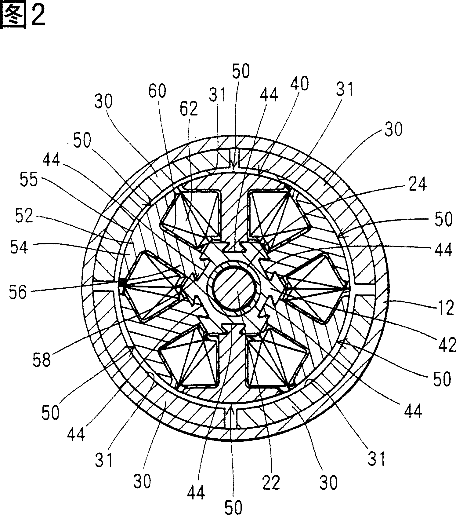
[0034] At the outer edge of the disc impeller 20, a plurality of fin grooves are formed. When the impeller 20 rotates with the armature 40, a pressure difference is generated between the front and rear of the vane slot due to fluid friction. By repeatedly pressurizing the vane slots, the pressure of the fuel in the pump passage 102 is increased. Due to the rotation of the impeller 20, the fuel is sucked in from...

no. 2 example and

[0060] [Second Embodiment and Third Embodiment]

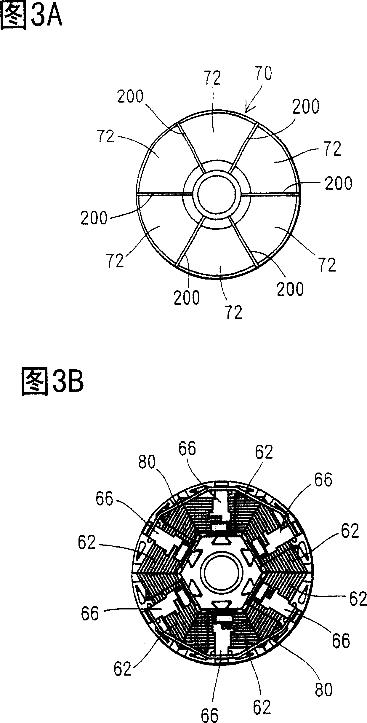
[0061] Referring to Fig. 13 and Fig. 14, except that the connection relationship between the coil 62 and the sector 72, and the connection relationship between each coil 62 are different, the structures of the second embodiment and the third embodiment are the same as those of the first embodiment The structures basically correspond. In the first embodiment, the ends of the respective coils 62 are connected together on the side of the armature 40 remote from the commutator 70 , that is, outside the commutator 70 . On the other hand, in the second embodiment, the ends of the coil 62 are electrically connected to the sector 72 in the commutator 90, and the other ends of the coil 62 are also connected to each other in the commutator 90. of. In the wiring relationship in the second embodiment, coil (a1) 62 and coil (a2) 62, coil (b1) 62 and coil (b2) 62, and coil (c1) 62 and coil (c2) 62 are respectively connected in series to T...


PUM


Abstract

The invention discloses a fuel pump. In a fuel pump, four permanent magnets are installed in a housing. An armature is installed inside the permanent magnets rotatably. Six magnetic pole coil portions of the armature are installed in a central core. Each magnetic pole coil portion has a coil core, a bobbin and a coil formed by winding a winding on the bobbin in a concentrated winding form. Each coil core has an outer region in opposition to the permanent magnet in a direction of revolution, and a board-shaped coil-winding portion extending from the outer region toward the central core. Each bobbin covers the coil core except for the outer surface of the outer region and a convex portion.

Description

technical field [0001] The invention relates to a fuel pump which feeds fuel drawn from a fuel tank to an internal combustion engine. Background technique [0002] In a fuel pump for sucking fuel from a fuel tank and delivering fuel to an engine, a plurality of permanent magnets are arranged in a circumferential direction of a fuel pump housing, and an armature is rotatably arranged inside the permanent magnets. In this way, a drive motor is installed in the fuel pump (see JP-B2-Hei 7-85642). In the armature, a plurality of pole coil portions are formed in the direction of rotation. The individual pole coil sections are produced by distributively winding the turns on a bobbin which encloses a coil core made of magnetic material. Power is supplied to each coil using a commutator divided into sectors, creating repulsive and attractive forces between the armature and each permanent magnet. Thus, due to the torque generated on the armature, the armature turns. [0003] In or...

Claims


Application Information

Patent Timeline
Patent Type & Authority Patents(China)
IPC IPC(8): H02K23/66F04D5/00F02M37/10F02M37/08F04D13/06H02K1/17H02K1/24H02K1/30H02K3/18H02K3/52H02K13/04H02K23/04H02K23/30
CPCF02M37/048H02K23/30H02K13/04H02K1/30H02K3/527F04D13/0673F04D5/002F02M37/08
Inventor 诸户清规伊藤元也岩成荣二
Owner DENSO CORP
Why Eureka
Try Eureka