Chuck plate, annealing device, and annealing method

Active Publication Date: 2020-10-01
SUMITOMO HEAVY IND LTD
View PDF0 Cites 0 Cited by
  • Summary
  • Abstract
  • Description
  • Claims
  • Application Information

AI Technical Summary

Benefits of technology

The patent describes a plate that is placed between an object and a table for holding it. This plate is designed to reduce the amount of heat that is emitted from the object and directed towards the table. The technical effect is that it helps to keep the object cool while it is being heated.

Problems solved by technology

For example, in a case where the semiconductor wafer is held and heated through a chuck plate on a holding table, it has become clear that a phenomenon of degradation of measurement accuracy occurs due to the shape or the like of the chuck plate or the holding table below the semiconductor wafer.

Method used


Image

  • Chuck plate, annealing device, and annealing method
  • Chuck plate, annealing device, and annealing method
  • Chuck plate, annealing device, and annealing method

Examples


Embodiment Construction

[0022]It is desirable to provide a chuck plate, an annealing device, and an annealing method capable of increasing accuracy of temperature measurement with detection of thermal radiation light.

[0023]It is possible to attenuate thermal radiation light directed downward from the annealing object, reflected by the holding table, transmitted through the chuck plate and the annealing object, and directed upward. As a result, the measurement of the intensity of thermal radiation light is hardly affected by the chuck plate or the holding table.

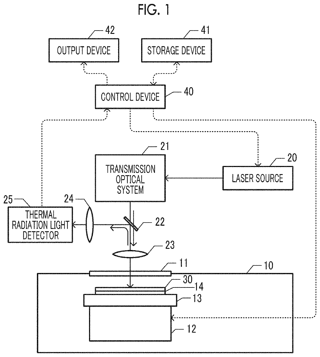
[0024]A laser annealing device according to an embodiment will be described referring to FIGS. 1, 2A, and 2B.

[0025]FIG. 1 is a schematic view of the laser annealing device according to the embodiment. A holding table 13 is supported in a chamber 10 by a scanning mechanism 12. The scanning mechanism 12 can move the holding table 13 within a horizontal plane with reception of a command from a control device 40. The scanning mechanism 12 includes an enc...


PUM


Abstract

A chuck plate is disposed between an annealing object and a holding table. The chuck plate has a function of attenuating thermal radiation light radiated from the annealing object and directed toward the holding table. The use of the chuck plate makes it possible to increase the accuracy of temperature measured by detection of thermal radiation light.

Description

RELATED APPLICATIONS[0001]The contents of Japanese Patent Application Nos. 2017-240419 and 2017-240420, and of International Patent Application No. PCT / JP2018 / 042511, on the basis of each of which priority benefits are claimed in an accompanying application data sheet, are in their entirety incorporated herein by reference.BACKGROUNDTechnical Field[0002]Certain embodiments of the present invention relate to a chuck plate, an annealing device, and an annealing method.Description of Related Art[0003]The related art discloses a technique for measuring a temperature of a surface of a semiconductor in rapidly heating a semiconductor wafer using a flash lamp annealing method. For example, the temperature of the semiconductor surface can be measured by detecting thermal radiation light from a semiconductor wafer surface.[0004]In measuring a surface temperature of the semiconductor wafer by detecting thermal radiation light from the semiconductor wafer, a situation in which an accurate temp...

Claims


Application Information

Patent Timeline
IPC IPC(8): H01L21/268H01L21/66H01L21/67
CPCH01L21/268H01L22/12H01L21/67115H01L21/683H01L21/68757H01L21/67248
Inventor TANAKA, TEPPEI
Owner SUMITOMO HEAVY IND LTD
Why Eureka
Try Eureka