Hygroscopic liquid hair roller

Inactive Publication Date: 2020-10-08
JOHNSON LONNIE G
View PDF0 Cites 1 Cited by
  • Summary
  • Abstract
  • Description
  • Claims
  • Application Information

AI Technical Summary

Benefits of technology

The invention is a hair roller that has a removable clip attached to it. The roller has a support structure with a cover that defines a chamber for a hygroscopic fluid material. The clip has its own support structure with a cover that defines a chamber for a hygroscopic fluid material. This design allows for easy removal and replacement of the clip without needing to replace the whole roller. The technical effect of this invention is that it provides a convenient and flexible way to use a hair roller with a hygroscopic fluid material for different hair styling needs.

Problems solved by technology

Once wet hair is wrapped about the roller the moisture within the hair is absorbed by the desiccant material thereby causing an exothermic reaction which creates heat that further dries the hair.
With this construction the area of desiccant material exposed to moisture is limited to its exterior surface.
This greatly reduces the capacity of the roller in absorbing moisture and producing heat.
The clay however limits the exposure of the silicate and therefore its function.
Another problem associated with this hollow interior design roller is that the pellets naturally gather within the bottom portion of the roller interior.
This can cause the uneven drying and curling of the hair.
It has been discovered however that the surface of the silica gel to which the adhesive is applied does not absorb moisture, and thus again the efficiency of the silica gel is limited.
A common problem with all of the previous hair drying roller attempts has been a limitation of the depth into which moisture penetrates into the moisture absorbent material within the rollers and thereby a limitation to the extent to which moisture can be absorbed from the hair.
This is a very slow process, particularly considering the desire to dry the hair at ambient temperatures and without the use of heat.
The main problem with that structure is that once the hair is curled onto the roller and the retaining cover is mounted in place, the structure is thereafter ridged and there is no flowing or movement of the moisture absorbing granules.
The problem of slow diffusion of moisture vapor remains and therefore limited drying.

Method used

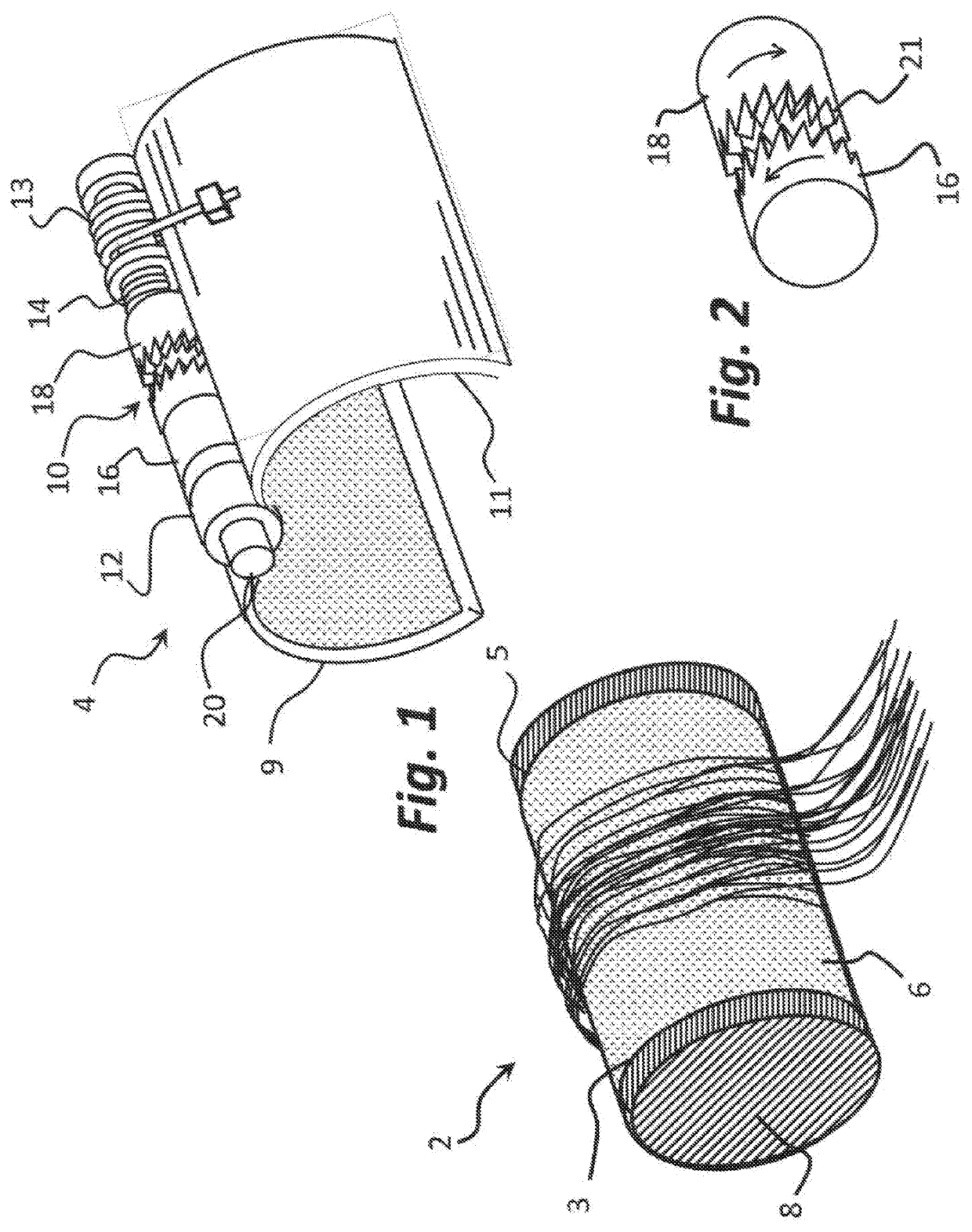
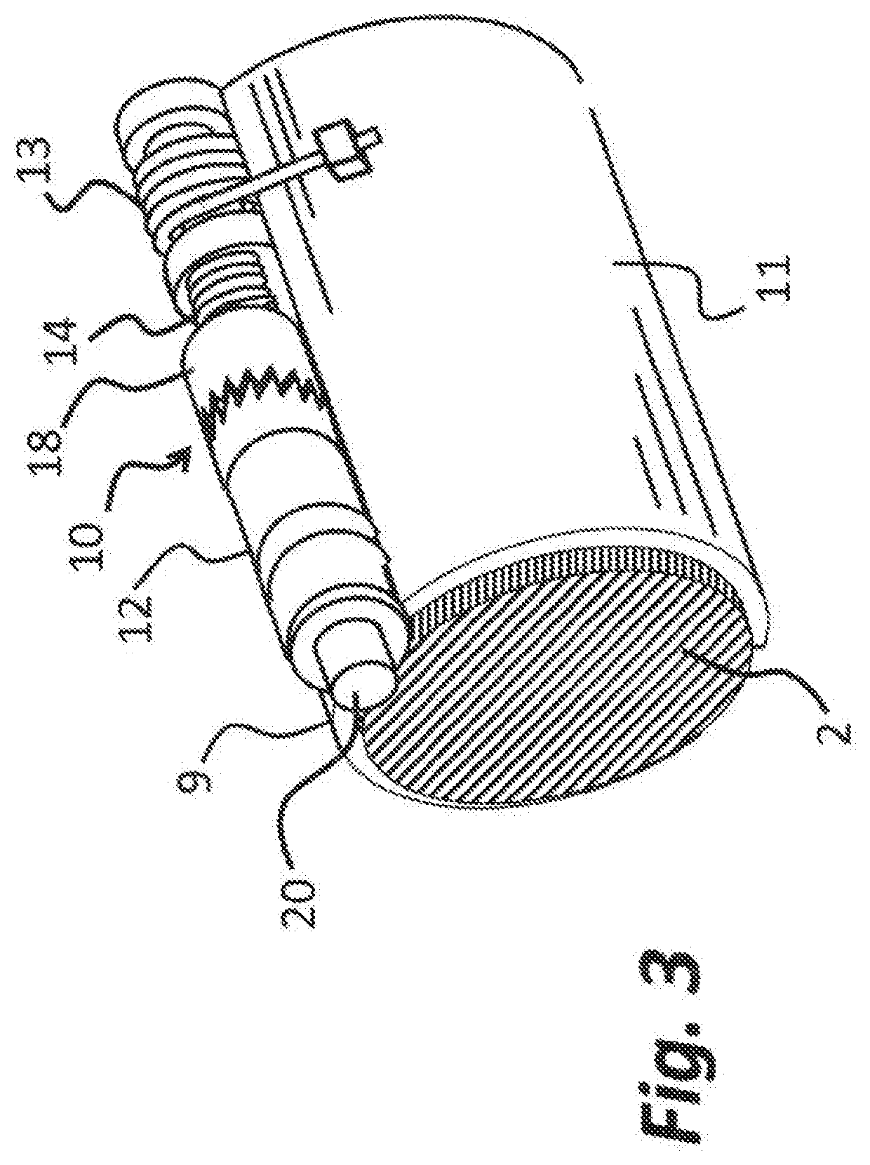
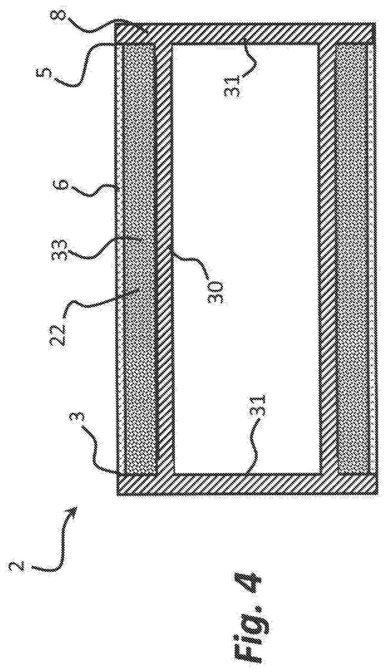

Image

  • Hygroscopic liquid hair roller
  • Hygroscopic liquid hair roller
  • Hygroscopic liquid hair roller

Examples


Embodiment Construction

Definitions

[0017]For purposes of the present disclosure, it is noted that spatially relative terms, such as “up,”“down,”“right,”“left,”“beneath,”“below,”“lower,”“above,”“upper” and the like, may be used herein for ease of description to describe one element or feature's relationship to another element(s) or feature(s) as illustrated in the figures. It will be understood that the spatially relative terms are intended to encompass different orientations of the device in use or operation in addition to the orientation depicted in the figures. For example, if the device in the figures is turned over or rotated, elements described as “below” or “beneath” other elements or features would then be oriented “above” the other elements or features. Thus, the exemplary term “below” can encompass both an orientation of above and below. The device may be otherwise oriented (rotated 90 degrees or at other orientations) and the spatially relative descriptors used herein interpreted accordingly.

Desc...


PUM


Abstract

A hair roller is disclosed having a roller portion and a retaining clip. The roller has a support structure and a tubular moisture permeable hydrophobic cover. The retaining clip is omega-shaped having two halves and a hinge with a first spring and a ratchet mechanism that maintains the clip in closed. The roller support structure includes a core and two end caps or ends. The roller cover forms a cavity with support structure to enclose a first hygroscopic material. The retaining clip also includes a mass of hygroscopic material contained within a chamber formed between a frame and a second moisture permeable hydrophobic cover.

Description

CROSS REFERENCE TO RELATED APPLICATIONS[0001]This application claims the benefit of U.S. Provisional Patent Application Ser. No. 62 / 829,138 filed April 4, 2019 and entitled Hygroscopic Liquid Hair Roller.STATEMENT REGARDING FEDERALLY SPONSORED RESEARCH OR DEVELOPMENT[0002]Not applicable.THE NAMES OF THE PARTIES TO A JOINT RESEARCH AGREEMENT[0003]Not applicable.TECHNICAL FIELD OF THE INVENTION[0004]The present inventive concept relates to the field of hair rollers. More particularly, the invention relates to a hygroscopic hair roller used to dry and roll hair.BACKGROUND OF THE INVENTION[0005]Hair treating devices are well known in the form of rollers which are typically cylindrical and sized so that a lock of hair may be wound thereabout for curling purposes. Such rollers have been made from a variety of material and have been used for both professional and home-use hair treatments.[0006]Hair drying rollers have also been previously proposed as a means for drying hair simultaneously ...

Claims


Application Information

Patent Timeline
IPC IPC(8): A45D20/00A45D6/14
CPCA45D6/145A45D20/00
Inventor JOHNSON, LONNIE G.
Owner JOHNSON LONNIE G
Why Eureka
Try Eureka