Locking device for trailer hitches and method therefor

a technology for trailer hitches and locking devices, which is applied in the field of locking devices, can solve the problems of being the target of unauthorized use or theft, affecting the ability to attach a tractor vehicle to the locking device, and the device can be subject to theft and removal,

Inactive Publication Date: 2006-10-17
WYERS PHILIP W
View PDF25 Cites 33 Cited by
  • Summary
  • Abstract
  • Description
  • Claims
  • Application Information

AI Technical Summary

Benefits of technology

[0011]It is an object of the present invention to provide a new and useful locking device and method to secure to a coupler section of the trailer.

Problems solved by technology

However, when a trailer vehicle is disconnected from the towing vehicle, it may become the target of unauthorized use or theft.
Accordingly, it is also known to provide a locking structure that engages the hitch ball recess of a trailer hitch coupler and locks onto the trailer hitch coupler so that the locking device interferes with the ability to attach a tractor vehicle.
This device, however, can be subject to attack by a thief and removed simply by hammering the arms out of alignment or breaking the arms off of the device so that the cylinder, and thus the locking device, may be removed from the trailer hitch coupler.
Each of these devices are relatively bulky and complex and again are subject to attack by a thief due to the exposed parts.
While this device is rather compact, it still exposes the locking structure to attack by a thief.
While the above-referenced devices do, in fact, lock onto a trailer hitch coupler, they suffer other disadvantages in addition to those noted above.
For example, none of the devices disclosed in the above-referenced patents are readily adjustable for differently dimensioned trailer hitch couplers moreover, each relies on an independent padlock which can inadvertently be misplaced so that the locking structure becomes less useable until another padlock is obtained.

Method used


Image

  • Locking device for trailer hitches and method therefor
  • Locking device for trailer hitches and method therefor
  • Locking device for trailer hitches and method therefor

Examples


Embodiment Construction

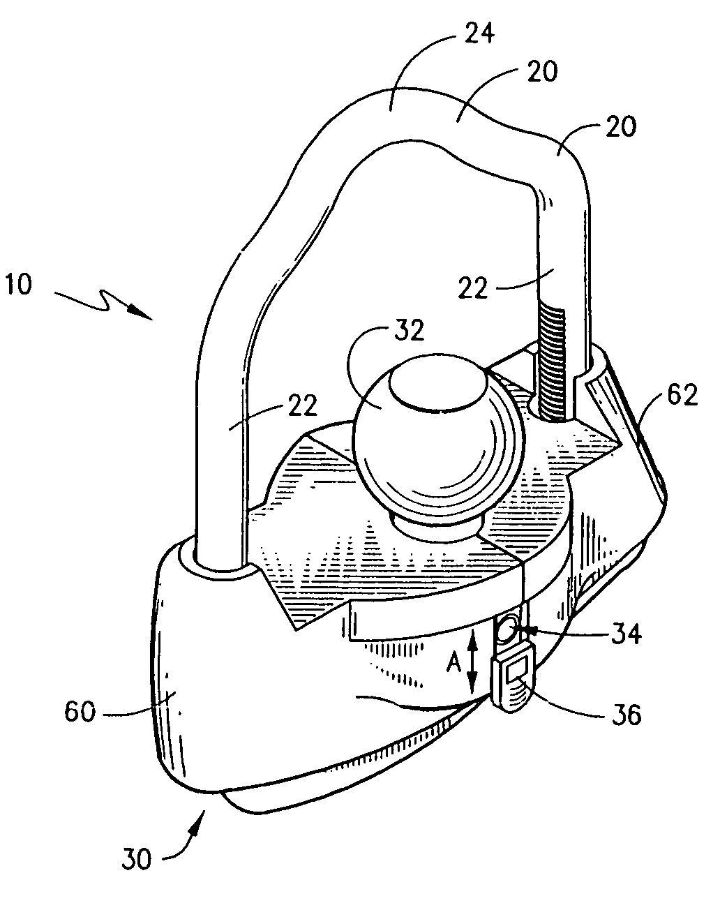
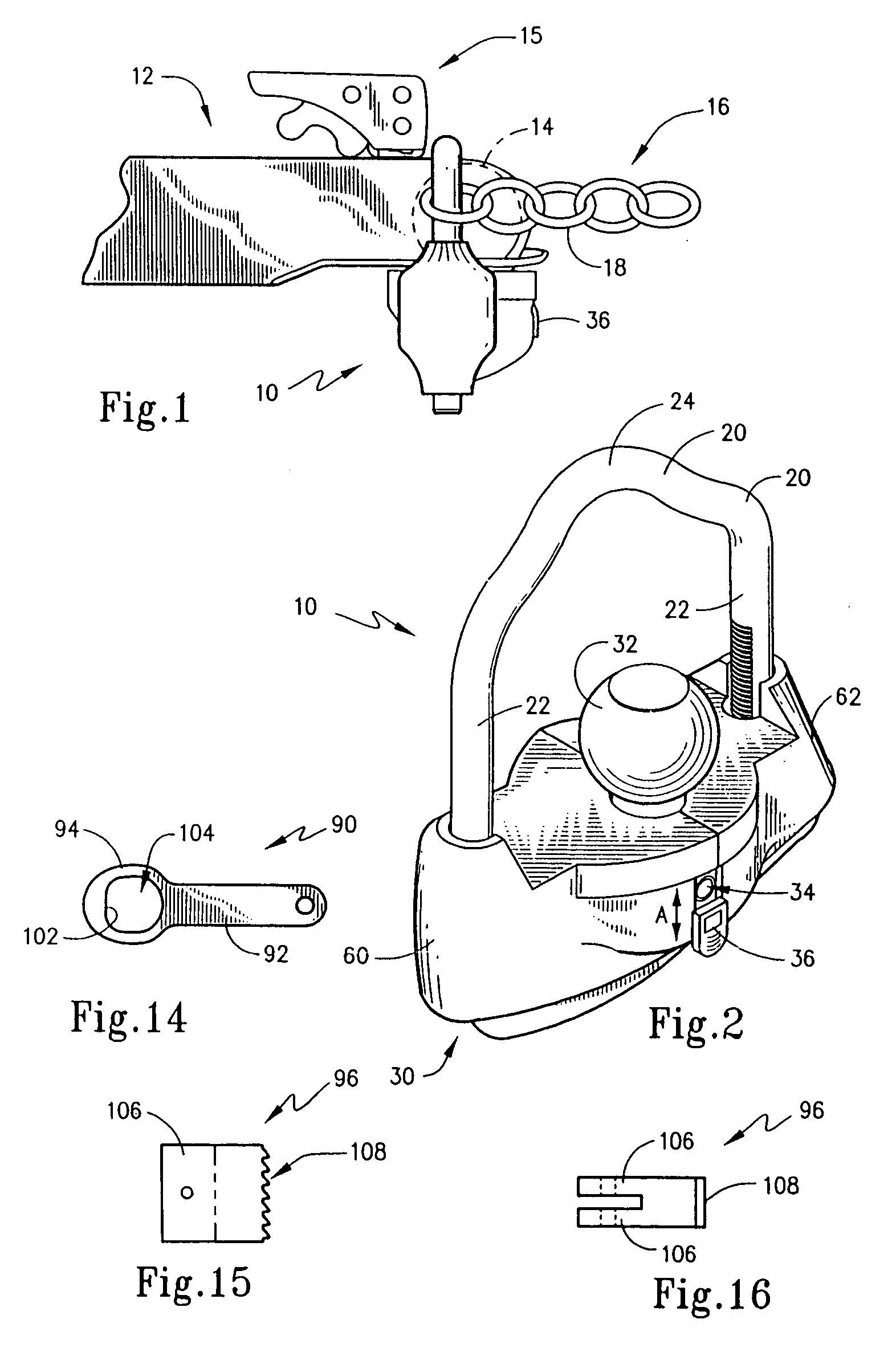
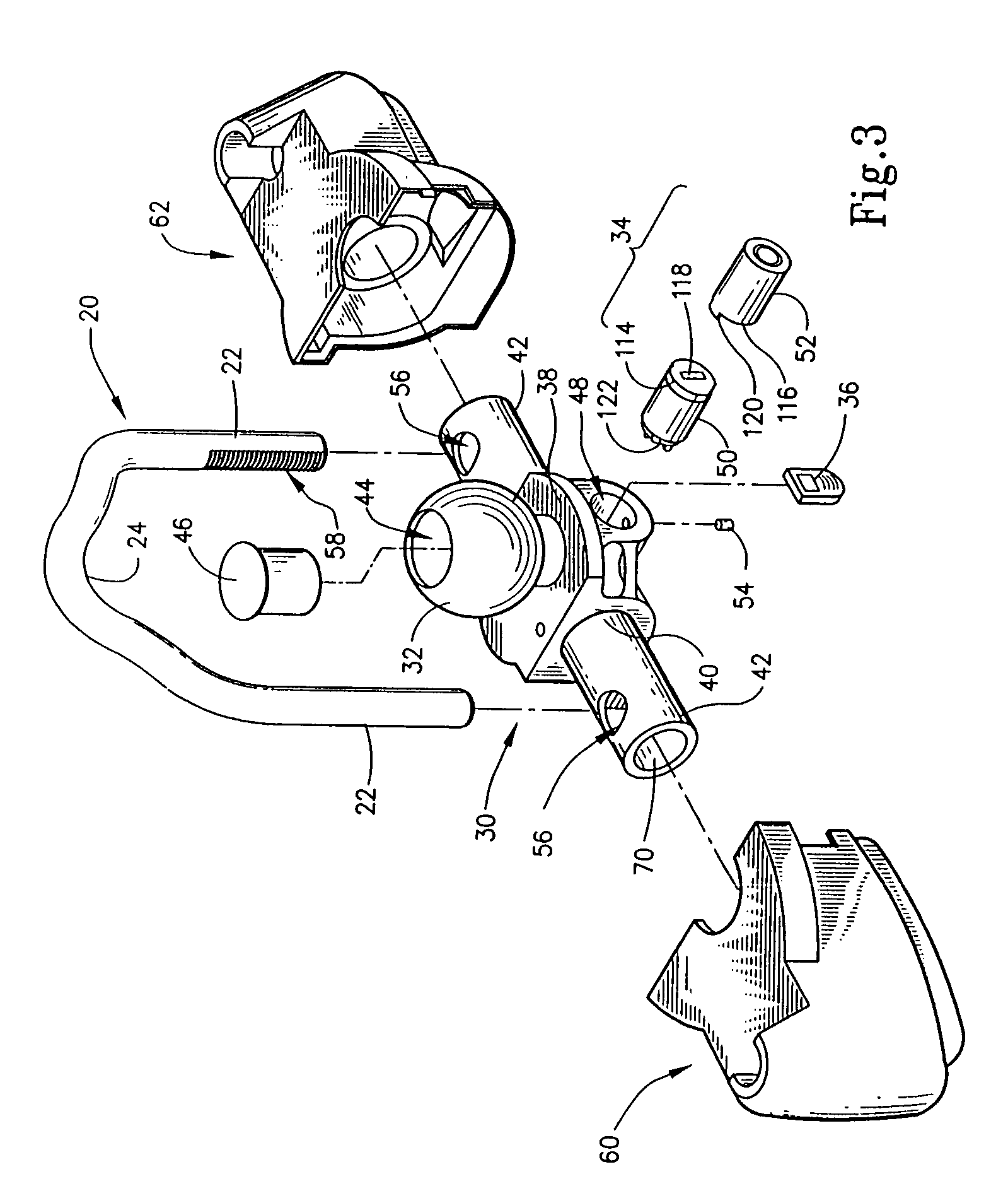
[0041]The present invention broadly concerns locks and locking devices adapted to secure an object. The present invention is particularly concerned with a locking device that is adapted to secure to the coupler section of a trailer that has a hitch ball recess so as to prevent attachment of the trailer hitch coupler to a towing vehicle when the locking device is secured thereto. This locking device also permits the securing of the coupler section of the trailer to a stationary object to prevent unauthorized use or theft of the trailer.

[0042]With reference now to FIG. 1, locking device 10 is introduced and is shown secured to a coupler section 12 of a trailer (not shown). Coupler section 12 typically forms part of the tongue of a trailer (not shown) and includes a recess 14 (shown in phantom) which is adapted to receive the hitch ball of a towing vehicle. An engagement mechanism 15, as is known, is provided to engage a hitch ball during use but can release to allow removal of the hit...


PUM


Abstract

A method and apparatus to secure the coupler section of a trailer provides a locking device that includes a lock housing having a hitch ball element to engage the recess in the coupler, a shackle member lockable to the housing and having a bridge section that spans the hitch ball element, and a latch assembly to latch and unlatch the shackle member. The shackle member is shown to be U-shaped with legs that extend through and secure to the lock housing. The latch assembly provides a ratchet-type engagement to allow adjustable locking. A rotatable lock mechanism drives a cam based latch mechanism between a latch state and an unlatch state.

Description

CROSS REFERENCE TO RELATED APPLICATIONS[0001]This application claims the benefit of U.S. Provisional Application No. 60 / 363,999 filed Mar. 13, 2002.FIELD OF THE INVENTION[0002]The present invention broadly concerns locking devices operative to prevent unauthorized access, theft or unauthorized use of objects. More particularly, however, the present invention is directed to a locking device to prevent the theft or unauthorized use of a trailer. The present invention specifically concerns a locking device which mates with the hitch recess in a trailer coupler so as to preclude access to that hitch and to secure the trailer to a stationary, relatively immoveable object.BACKGROUND OF THE INVENTION[0003]The use of towable vehicles has become increasingly popular for both utilitarian and pleasure purposes. A wide variety of both tractor and trailer vehicles are employed for general or special purposes. Tractor vehicles, for example, include both those that travel on road, such as cars, sp...

Claims


Application Information

Patent Timeline
Patent Type & Authority Patents(United States)
IPC IPC(8): B60R25/00B60D1/06B60D1/60
CPCB60D1/065B60D1/60Y10T70/40Y10T70/409Y10T70/454Y10T70/459Y10T70/5876Y10T70/5982
Inventor WYERS, PHILIP W.
Owner WYERS PHILIP W
Why Eureka
Try Eureka