Heat dissipation assembly and portable electronic device
- Summary
- Abstract
- Description
- Claims
- Application Information
AI Technical Summary
Benefits of technology
Problems solved by technology
Method used
Image

Examples
first embodiment
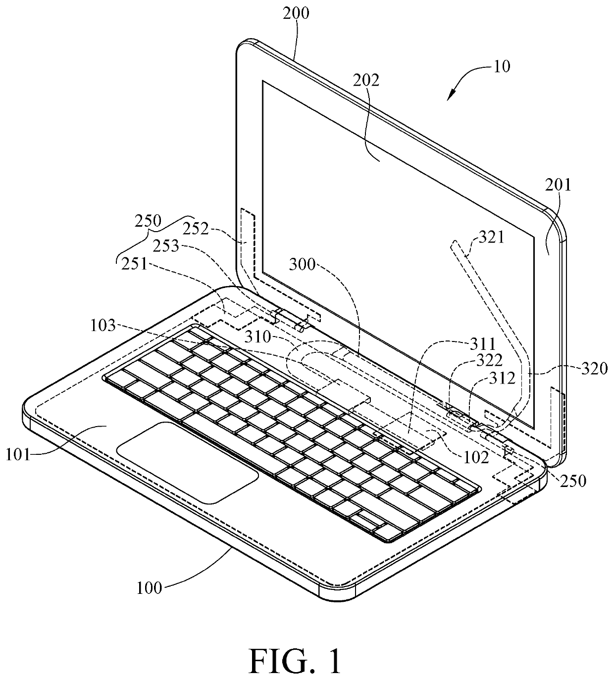
[0020]Please refer to FIG. 1. FIG. 1 is a perspective view of a portable electronic device according to the disclosure.
[0021]This embodiment provides a portable electronic device 10 including a host body 100, a display body 200, two hinges 250, and a heat dissipation assembly 300.
[0022]The host body 100 includes a base 101, a heat source 102, and a heat dissipation component 103. The heat source 102 is disposed in the base 101 and may be a central processing unit. The heat dissipation component 103 is disposed in the base 101.
[0023]The display body 200 includes a metal casing 201 and a display panel 202. The metal casing 201 is pivotably connected to the base 101 via the hinges 250 so that the metal casing 201 can be pivoted relative to the base 101, allowing the user to close or open the portable electronic device 10. The display panel 202 is disposed on the metal casing 201.
[0024]In detail, each hinge 250 has a single axis and includes a first mounting part 251, a second mounting ...
second embodiment
[0033]The first outer peripheral wall is not limited to contact the inner peripheral wall, please refer to FIG. 6, FIG. 6 shows a cross-sectional side view of a second end part of a first heat pipe of a portable electronic device according to the disclosure. One of differences between the previous embodiments and this embodiment is the position of the first outer peripheral wall relative to the inner peripheral wall. For the purpose of brevity, the descriptions of the same or similar parts of these embodiments are omitted and can be referred to the previous embodiments. In this embodiment, an inner peripheral wall 3121a of a second end part 312a of a first heat pipe 310a is not in contact with a first outer peripheral wall 3120a of a second end part 312a. As shown in FIG. 6, there is a gap G between the first outer peripheral wall 3120a of the second end part 312a and the inner peripheral wall 3121a.
[0034]The insertion hole is not limited to be located on the geometry center of the...
fourth embodiment
[0035]In addition, the shape of the first outer peripheral wall is not particularly limited. Please refer to FIG. 8. FIG. 8 is a cross-sectional side view of a second end part of a first heat pipe of a portable electronic device according to the disclosure. One of differences between the previous embodiments and this embodiment is the shape of the first outer peripheral wall. For the purpose of brevity, the descriptions of the same or similar parts of these embodiments are omitted and can be referred to the previous embodiments. In this embodiment, a shape of a radial cross section of a first outer peripheral wall 3120c of a second end part 312c of a first heat pipe 310c may be ecliptic so that the first outer peripheral wall 3120c has non-circular radial cross section.
PUM
 Abstract
Description
Claims
Application Information
 - R&D Engineer
- R&D Manager
- IP Professional
- Industry Leading Data Capabilities
- Powerful AI technology
- Patent DNA Extraction
Browse by: Latest US Patents, China's latest patents, Technical Efficacy Thesaurus, Application Domain, Technology Topic.
© 2024 PatSnap. All rights reserved.Legal|Privacy policy|Modern Slavery Act Transparency Statement|Sitemap