
Steering system

a steering system and steering mechanism technology, applied in the direction of electric steering, fluid steering, vehicle components, etc., can solve the problems of increasing the energy consumption of supplying working fluid, and the inability of steering the wheel by the steering mechanism, so as to improve the utility of the steering system, and supply flow rate always high

Active Publication Date: 2020-10-15
TOYOTA JIDOSHA KK +1
View PDF12 Cites 0 Cited by
  • Summary
  • Abstract
  • Description
  • Claims
  • Application Information

AI Technical Summary

Benefits of technology

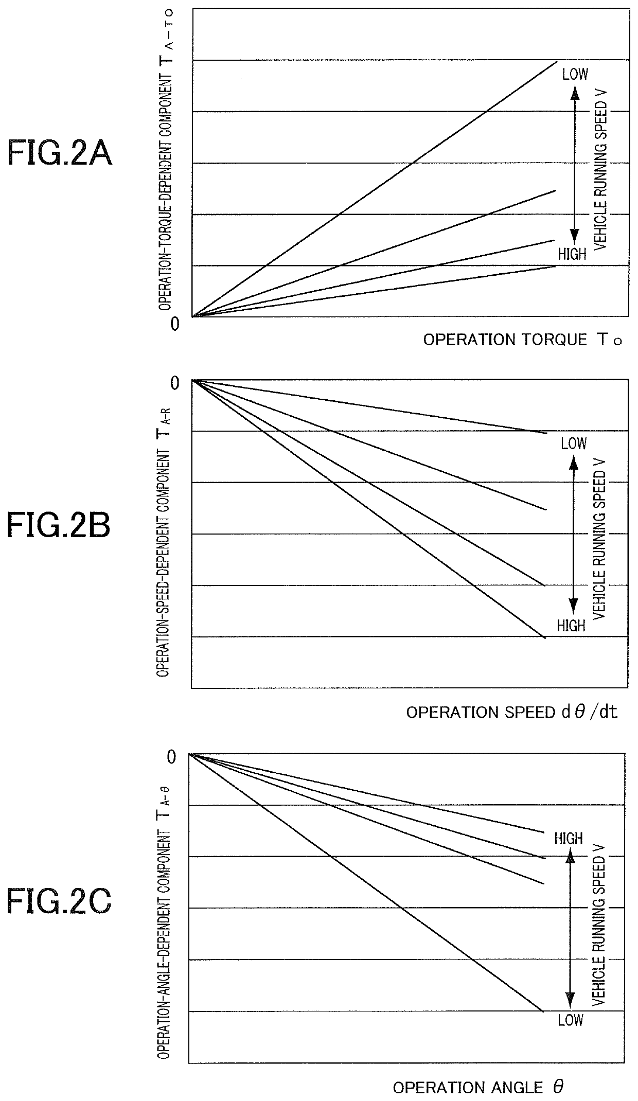
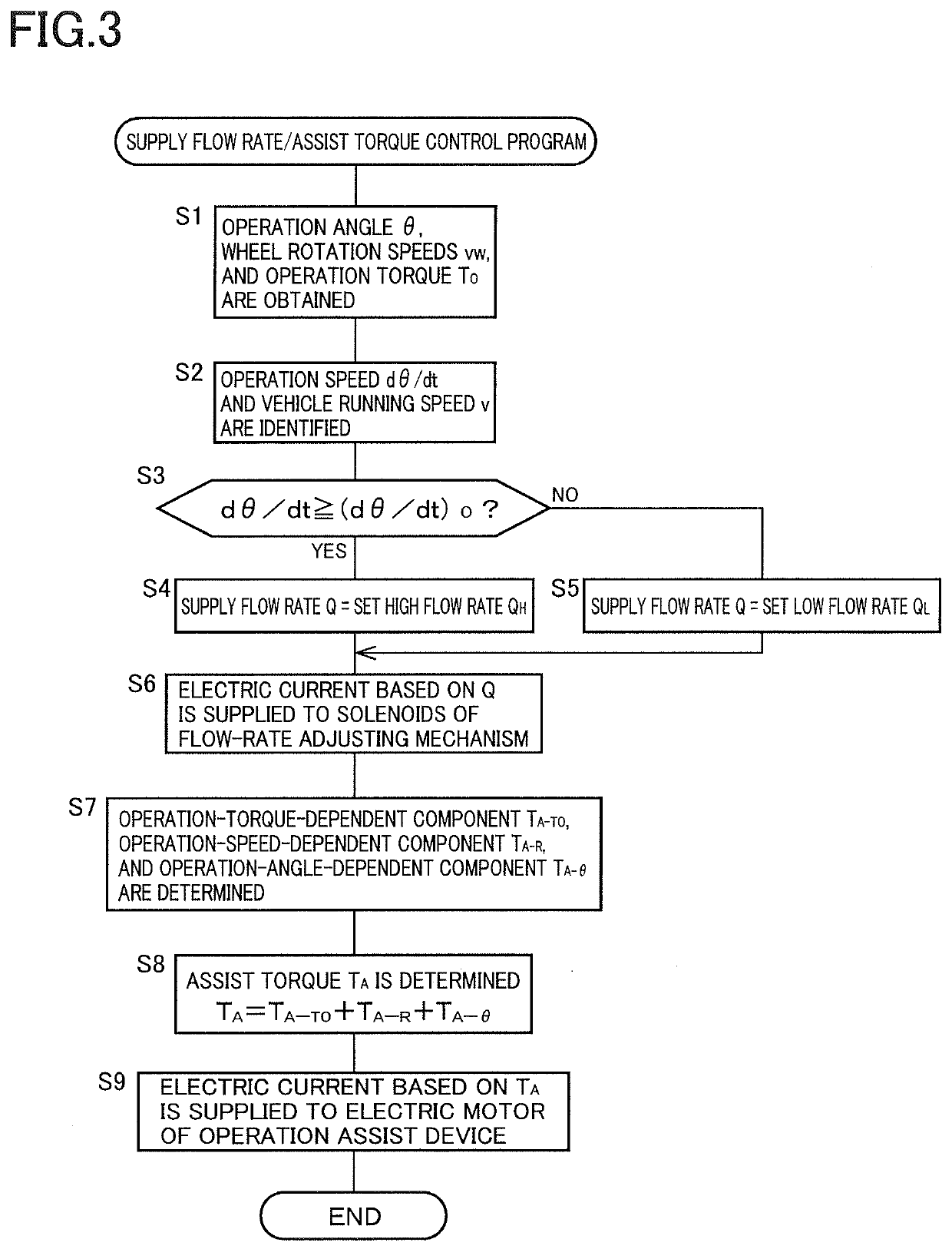
The present patent is about a steering system for vehicles that includes two assist devices: an operation assist device and a steering assist device. The operation assist device applies a torque to the steering shaft to reduce the driver's load and improve operational feeling. The steering assist device helps move the steering member. The system uses an electric pump to supply the working fluid to the steering assist device, which can increase energy consumption. To address this, the system controls the supply flow rate of the working fluid based on the operation speed of the steering operation member and the vehicle's running speed. By increasing the supply flow rate when the operation speed is high, the system prevents delay in steering while reducing energy consumption. The system also includes an assist torque that is applied by the operation assist device to further improve operational feeling. The source of the assist torque can be an electric motor, which makes the system more responsive and reliable. Overall, the system has high utility and can be used in various steering assist devices.

Problems solved by technology

However, keeping the supply flow rate always high undesirably increases energy consumption for supplying the working fluid to a considerable extent.
When the operation speed is relatively high, in contrast, it is highly likely that the steering of the wheel by the steering mechanism cannot follow the operation of the steering operation member.

Method used


Image

  • Steering system
  • Steering system
  • Steering system

Examples


Embodiment Construction

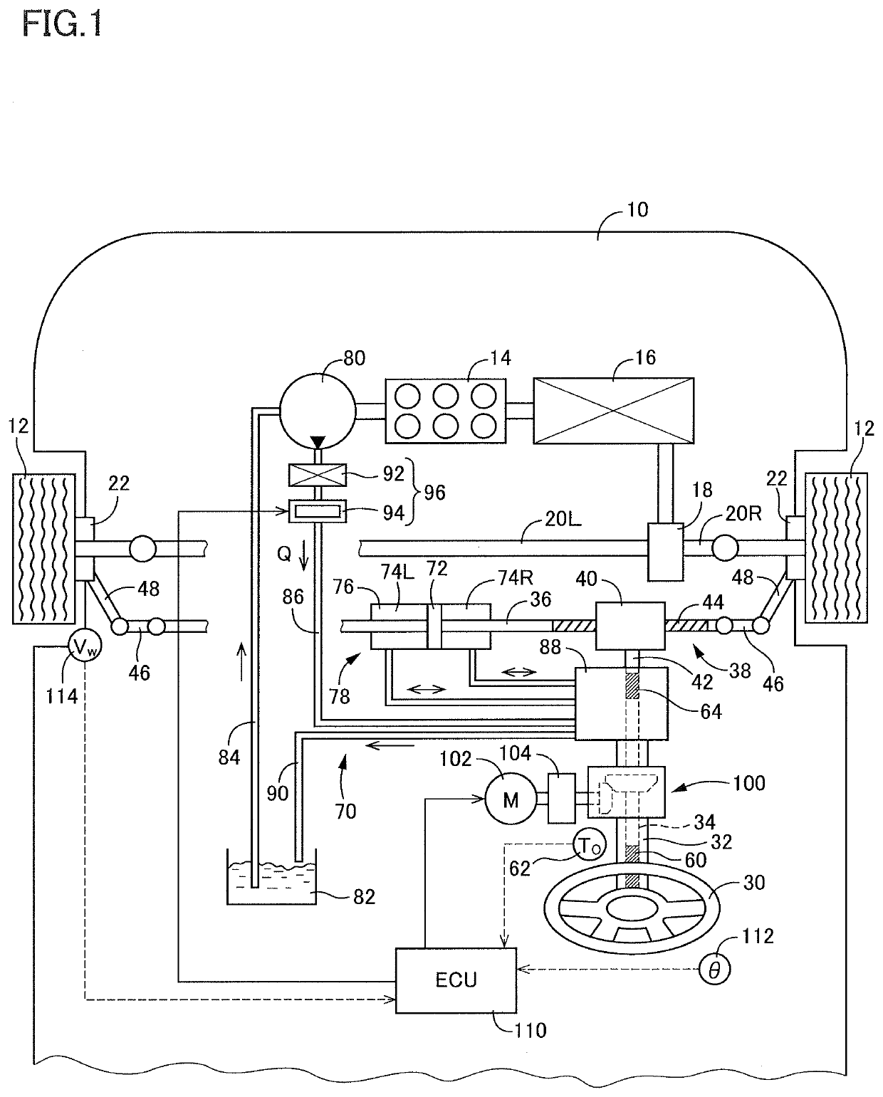
[0037]Referring to the drawings, there will be explained in detail a steering system according to one embodiment of the present disclosure. It is to be understood that the present disclosure is not limited to the details of the following embodiment but may be embodied based on the forms described in Various Forms and may be changed and modified based on the knowledge of those skilled in the art.

A. Hardware Configuration of Steering System

[0038]As illustrated in FIG. 1, a vehicle 10 on which is installed a steering system according to one embodiment includes two front wheels 12 each as a steerable wheel and as a drive wheel. The vehicle 10 includes an engine 14 as a drive source. Rotation of the engine 14 is transmitted to each of the front wheels 12 held by respective steering knuckles 22a via a torque converter / transmission 16, a differential 18, and respective drive shafts 20R, 20L. The vehicle 10 runs by the rotation of the front wheels 12.

[0039]The steering system according to t...


PUM


Abstract

A steering system installed on a vehicle, including: a steering mechanism including a steering member and configured to enable a wheel to be steered in accordance with a movement of the steering member; an operation assist device configured to apply a torque to a steering shaft for assisting an operation of a steering operation member; a steering assist device configured to assist the movement of the steering member utilizing a working fluid; and a controller configured to control a torque applied to the steering shaft by the operation assist device and control a supply flow rate of the working fluid, wherein the steering assist device assists the movement of the steering member with an assist force that depends on the supply flow rate, and the controller increases the supply flow rate when an operation speed of the steering operation member becomes equal to or higher than a set threshold speed.

Description

CROSS REFERENCE TO RELATED APPLICATION[0001]The present application claims priority to Japanese Patent Application No. 2019-077310, which was filed on Apr. 15, 2019, the disclosure of which is herein incorporated by reference in its entirety.BACKGROUNDTechnical Field[0002]The following disclosure relates to a steering system installed on a vehicle.Description of Related Art[0003]An ordinary steering system installed on a vehicle includes (a) a steering operation member operated by a driver, (b) a steering shaft coupled to the steering operation member and configured to rotate in accordance with an operation of the steering operation member, and (c) a steering mechanism including a steering member coupled to a wheel and configured to cause the steering member to move in accordance with rotation of the steering shaft so as to enable the wheel to be steered in accordance with a movement of the steering member. It has been proposed that such a steering system further include two assist ...

Claims


Application Information

Patent Timeline
IPC IPC(8): B62D5/04B62D7/16B62D5/06B62D6/02
CPCB62D5/063B62D5/0409B62D6/02B62D7/16B62D5/0463B62D5/064B62D5/065
Inventor AOKI, TOSHIMASAFUJITA, SHUJISATO, KOKIFUKUI, HIROKIIKEDA, TSUYOSHI
Owner TOYOTA JIDOSHA KK
Learn More