Aerosol generating device

a technology air flow path, which is applied in the direction of electric/magnetic/electromagnetic heating, lighting and heating apparatus, instruments, etc., can solve the problems of aerosol generating device performance degradation, increased air flow path, etc., and achieves the effect of smooth air flow and effectively preventing the performance degradation of the aerosol generating devi

Pending Publication Date: 2020-10-22
KT&G CO LTD
View PDF12 Cites 22 Cited by
  • Summary
  • Abstract
  • Description
  • Claims
  • Application Information

AI Technical Summary

Benefits of technology

[0005]The present disclosure may provide an aerosol generating device including a cover coupled to a body portion. Specifically, the aerosol generating device according to the present disclosure may include a body portion comprising a vaporizer for heating a liquid composition to generate an aerosol and one or more air flow paths for causing the generated aerosol to pass through a cigarette and discharged to the outside, and a cover coupled to the body portion and comprising a plurality of independent passages that guide air to an entrance of the vaporizer along at least a part of the surface of the body portion.
[0006]According to the present disclosure, the plurality of passages through which air is introduced into the vaporizer included in the aerosol generating device are formed, thereby achieving a smooth air flow in the aerosol generating device, and effectively preventing the performance degradation of the aerosol generating device.

Problems solved by technology

As a result, the air flow path may increase or may be more complex as compared to the related art.
In this case, if the number of air inlets is maintained to be the same as in the related art, the performance of the aerosol generating device may be degraded because of unsmooth air flow in the aerosol generating device.

Method used


Image

  • Aerosol generating device
  • Aerosol generating device
  • Aerosol generating device

Examples


Embodiment Construction

Solution to Problem

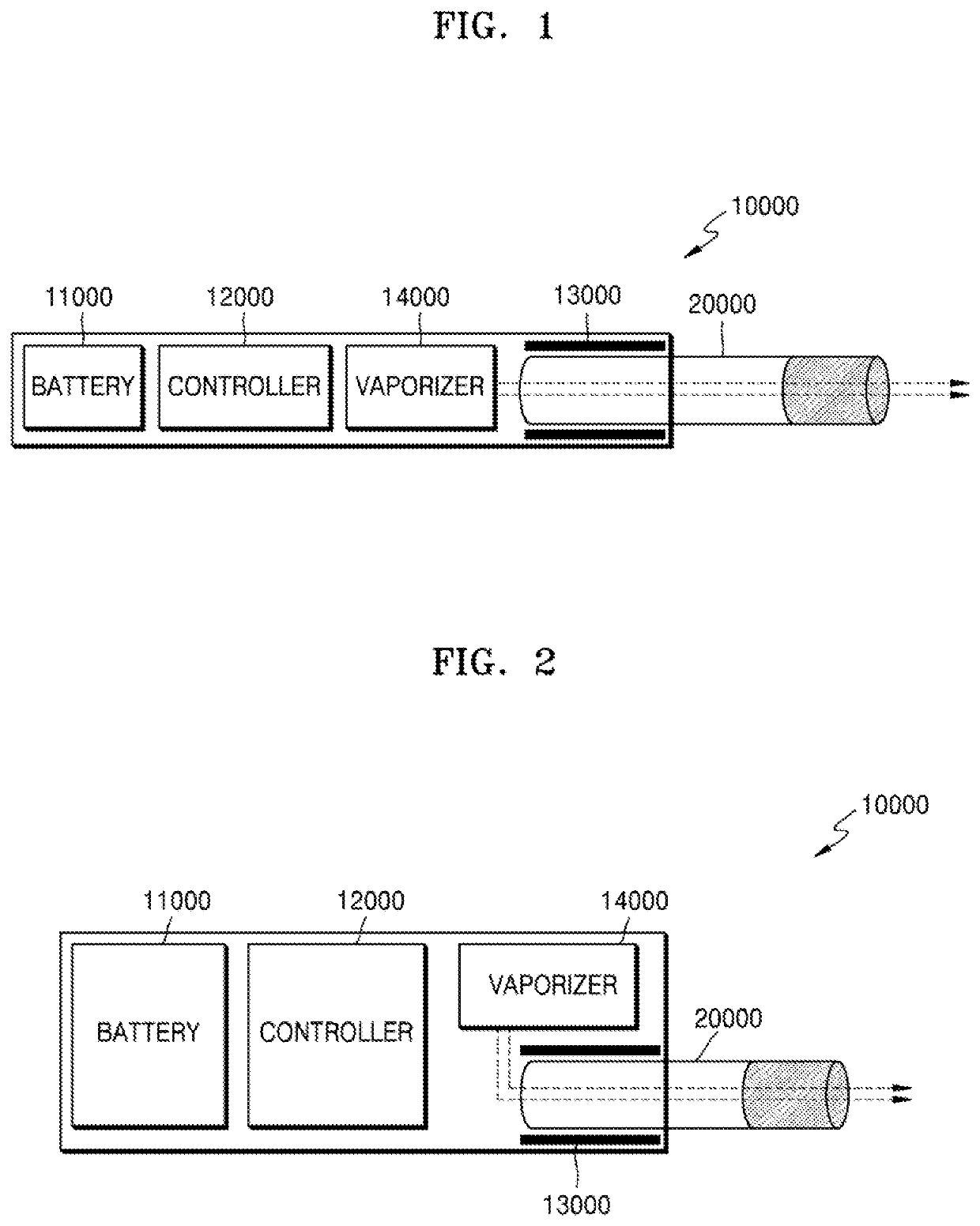
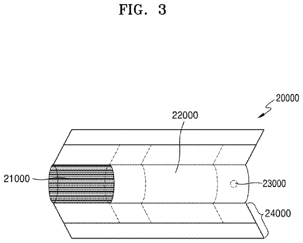
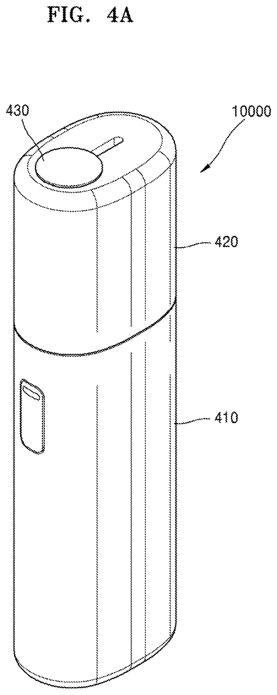
[0004]Provided are an aerosol generating device. The technical solution of the present disclosure is not limited to the above-described technical problems, and other technical problems may be deduced from the following embodiments. For example, an aerosol generating device may include a body portion comprising a vaporizer configured to heat a liquid composition to generate an aerosol and one or more air flow paths for causing the generated aerosol to pass through a cigarette and discharged to the outside, and a cover coupled to the body portion and comprising a plurality of passages comprising a first passage and a second passage which are independent from each other and guide air to an entrance of the vaporizer along at least a part of the surface of the body portion.

Advantageous Effects of Disclosure

[0005]The present disclosure may provide an aerosol generating device including a cover coupled to a body portion. Specifically, the aerosol generating device accord...


PUM

PropertyMeasurementUnit
melting point Tmaaaaaaaaaa
glass transition temperature Tgaaaaaaaaaa
widthaaaaaaaaaa

Abstract

According to an exemplary embodiment, provided is an aerosol generating device including a body portion comprising a vaporizer configured to generate aerosol by heating a liquid composition; and one or more air flow paths configured to cause the generated aerosol to pass through a cigarette and be discharged to outside; and a cover coupled to the body portion and comprising a plurality of passages comprising a first passage and a second passage which are independent from each other and guide air to an entrance of the vaporizer along at least part of a surface of the body portion.

Description

TECHNICAL FIELD[0001]The present disclosure relates to an aerosol generating device, and more particularly, to an aerosol generating device capable of generating an aerosol having various flavors by passing an aerosol generated by a vaporizer through a cigarette.BACKGROUND ART[0002]Recently, the demand for alternative methods to overcome the shortcomings of general cigarettes has increased. For example, there is an increasing demand for a method of generating aerosol by heating an aerosol generating material in cigarettes, rather than by burning cigarettes. Accordingly, studies on a heating-type cigarette and a heating-type aerosol generating device have been actively conducted.[0003]Meanwhile, to provide a user with an improved smoking experience, an aerosol generating device that uses a liquid composition as an aerosol generating source with a cigarette has been developed. For example, there has been developed an aerosol generating device which includes a vaporizer for heating a l...

Claims


Application Information

Patent Timeline
Patent Type & Authority Applications(United States)
IPC IPC(8): A24F40/485A24F40/10A24D3/17A24F40/20A24F40/30
CPCA24F40/30A24D3/17A24F40/10A24F40/20A24F40/485A24B15/167A24B15/302A24F40/40A24F40/46A24F40/48A24F40/50A24F40/51A24F40/53H05B1/0227H05B3/20H05B6/06H05B6/108A24F40/42A24F40/57A61M15/06A24F47/00F21Y2115/10A24F40/65A24F40/90A24F15/01A24F40/95A24F40/44A24D1/20A24F40/60F21V3/00F21V5/00G02B19/0009G02B19/0061H05B3/54H05K1/0203H05K1/0277H05K1/148H05K1/181H05K2201/012H05K2201/0154H05K2201/10219
Inventor KIM, TAE HUNPARK, JONG SUN
Owner KT&G CO LTD
Why Eureka
Try Eureka