Check patentability & draft patents in minutes with Patsnap Eureka AI!

Flow-path structure

a flow path and structure technology, applied in the direction of machines/engines, laminated elements, lighting and heating apparatus, etc., can solve the problems of gap between, achieve the effect of preventing the occurrence of an assembly error of the flow path structure, restricting the deformation of the barrel body towards the outside, and restricting the separation of the barrel body from the frame par

Active Publication Date: 2020-10-22
CALSONIC KANSEI CORP
View PDF0 Cites 1 Cited by
  • Summary
  • Abstract
  • Description
  • Claims
  • Application Information

AI Technical Summary

Benefits of technology

The present invention aims to prevent errors when assembling a flow-path structure. The invention achieves this by fitting a ring-shaped frame to the outer surface of a barrel body, which prevents deformation of the barrel body and restricts separation of the barrel body from the frame. This results in a gap-free assembly, reducing the likelihood of assembly errors.

Problems solved by technology

Therefore, an assembling error in which the air-intake-flow-path forming member is separated inwards from the connecting plates when the assembled body is subjected to the brazing, may cause a gap between them.

Method used


Image

  • Flow-path structure
  • Flow-path structure
  • Flow-path structure

Examples


Embodiment Construction

[0018]An embodiment of the present invention will be described below with reference to the attached drawings.

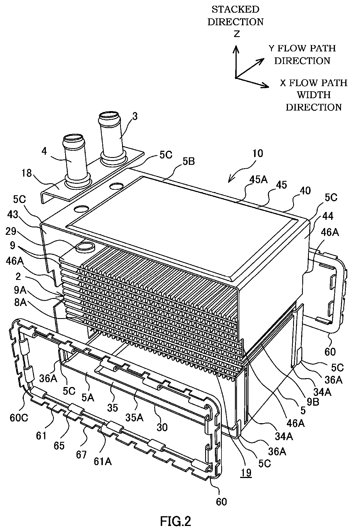
[0019]A heat exchanger 1 shown in FIG. 1 is used as a fluid-cooled charge air cooler for cooling intake air to be supercharged to an engine (not shown) with coolant liquid (coolant medium).

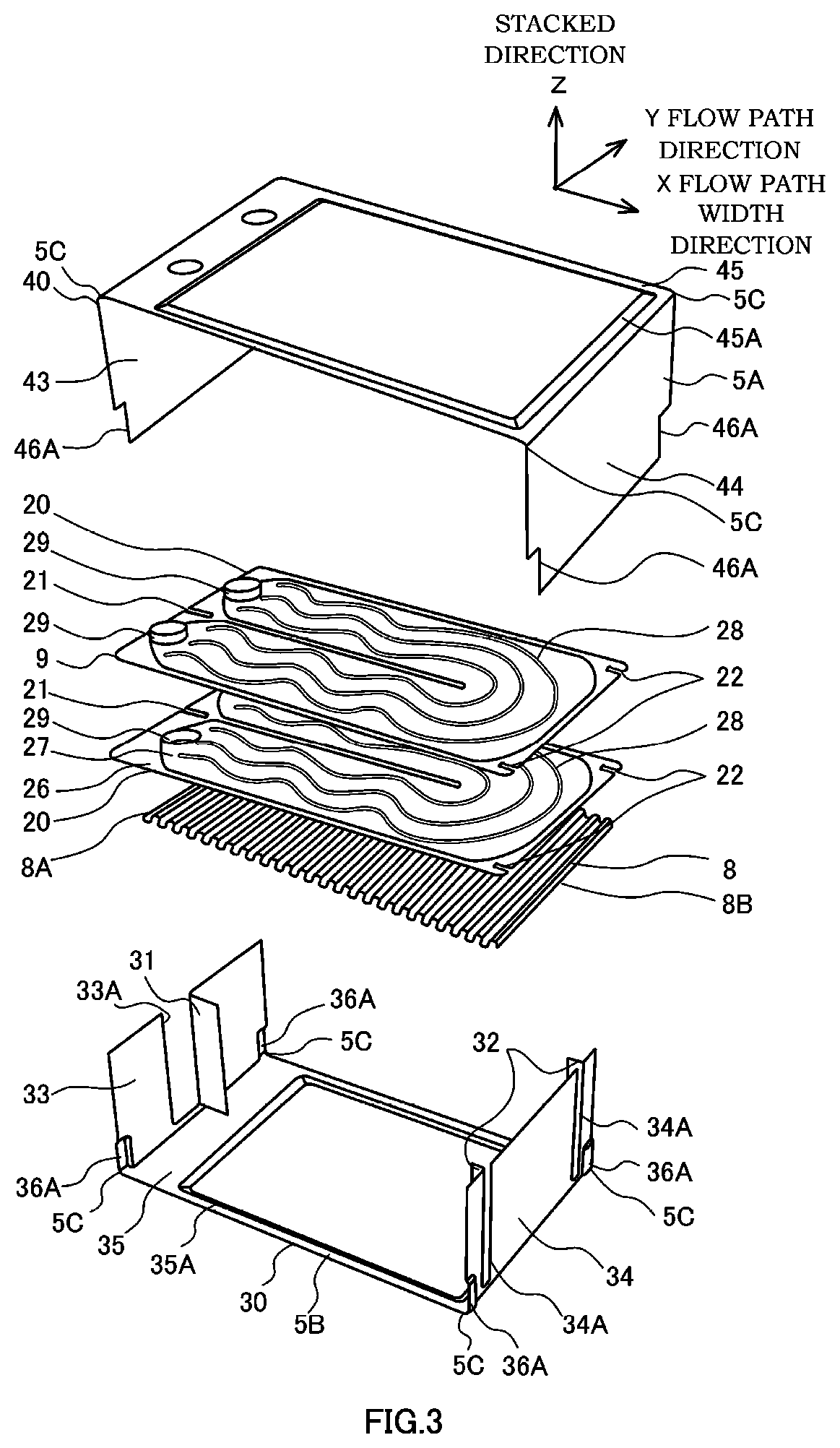
[0020]The heat exchanger 1 includes a barrel-shaped barrel body 5 having pipes 3 and 4 projecting out therefrom, a pair of ducts 6 and 7 connected to both opening ends of the barrel body 5, and a core 2 accommodated within the barrel body 5 (see FIG. 2).

[0021]The barrel body 5 and the ducts 6 and 7 form a flow-path structure through which the intake air (fluid) flows.

[0022]Air intake pipes (not shown) for the engine are connected to the ducts 6 and 7. When the engine is operated, the intake air flows through the air intake pipe and flows into the core 2 from the one duct 6 via the barrel body 5. The intake air flowing through the core 2 is cooled by releasing heat to the coolant liquid flow...


PUM


Abstract

A flow-path structure through which fluid flows includes: a barrel body through which fluid flows in an inner circumference; and a frame body configured to connect a flow path member, the flow path member being configured to guide the fluid into the barrel body, wherein the frame body has: a ring-shaped frame part configured to be fitted into an outer surface of the barrel body; and an inner engagement portion configured to engage with an inner surface of the barrel body so as to hold a state in which the outer surface of the barrel body is brought into contact with the frame part.

Description

TECHNICAL FIELD[0001]The present invention relates to a flow-path structure through which fluid flows.BACKGROUND ART[0002]JP2014-214955A discloses a heat exchanger that is used as an intercooler of an engine.[0003]The above-mentioned heat exchanger includes a core unit through which cooling fluid circulates, an air-intake-flow-path forming member that accommodates the core unit, and frame-shaped connecting plates that connect a duct to the air-intake-flow-path forming member. The intake air for the engine flows through the air-intake-flow-path forming member via the duct and is cooled by releasing the heat to the cooling fluid circulating in the core unit.[0004]When the above-mentioned heat exchanger is fabricated, an assembled body is formed by assembling the core unit, the air-intake-flow-path forming member, and the connecting plates. The assembled body is heated in a heating furnace, and thereby, the respective members are brazed to each other.[0005]Since frame shaped connecting...

Claims


Application Information

Patent Timeline
Patent Type & Authority Applications(United States)
IPC IPC(8): F02B29/04F28D7/16F28F9/00F28F9/18
CPCF28F9/18F28D7/16F28F9/00F02B29/04F28D9/0031F28D9/02F28D2021/0082F28F3/025F28F3/12Y02T10/12F28D7/1653F28F9/0219F28F9/0226
Inventor KATO, MASAHIROTAKIMOTO, KYOUHEIKANEDA, TAKASHI
Owner CALSONIC KANSEI CORP
Features
  • R&D
  • Intellectual Property
  • Life Sciences
  • Materials
  • Tech Scout
  • Unparalleled Data Quality
  • Higher Quality Content
  • 60% Fewer Hallucinations
Learn More