[0010]An object of the present invention is to provide a
lubrication device of a turbocharger of an engine for a vehicle which can increase the
layout flexibility around the engine, absorb the vibration move of the first and second turbochargers relative to the engine, absorb the positional error between the first and second turbochargers, and the like.
[0012]According to the present invention, since the
metal-made return passages of the first and second turbochargers are provided described above, the number of the return portion as the engine-side connection portion can be less than that of the return passages of the first and second turbochargers. Thereby, the return passages of the first and second turbochargers can be connected to the engine compactly by using a smaller layout space. Further, since only the one of the return passages is connected to the engine, the positional error of the other turbocharger relative to the engine does not influence this return passage, so that the assembly error of this return passage can be minimized Further, eve if the return passage of the second turbocharger is made from
metal having a
high heat resistance, the vibration move between the second turbocharger and the engine can be properly absorbed by the
bellows-shaped
vibration absorption portion. Moreover, since the flexible hose of the return passage of the first turbocharger can be shorter, the surface area exposed to the high temperature can be minimized Accordingly, the vibration move between the first turbocharger and the engine can be absorbed, preventing the heat damage of the flexible hose, so that the positional error between the first and second turbochargers can be absorbed properly.
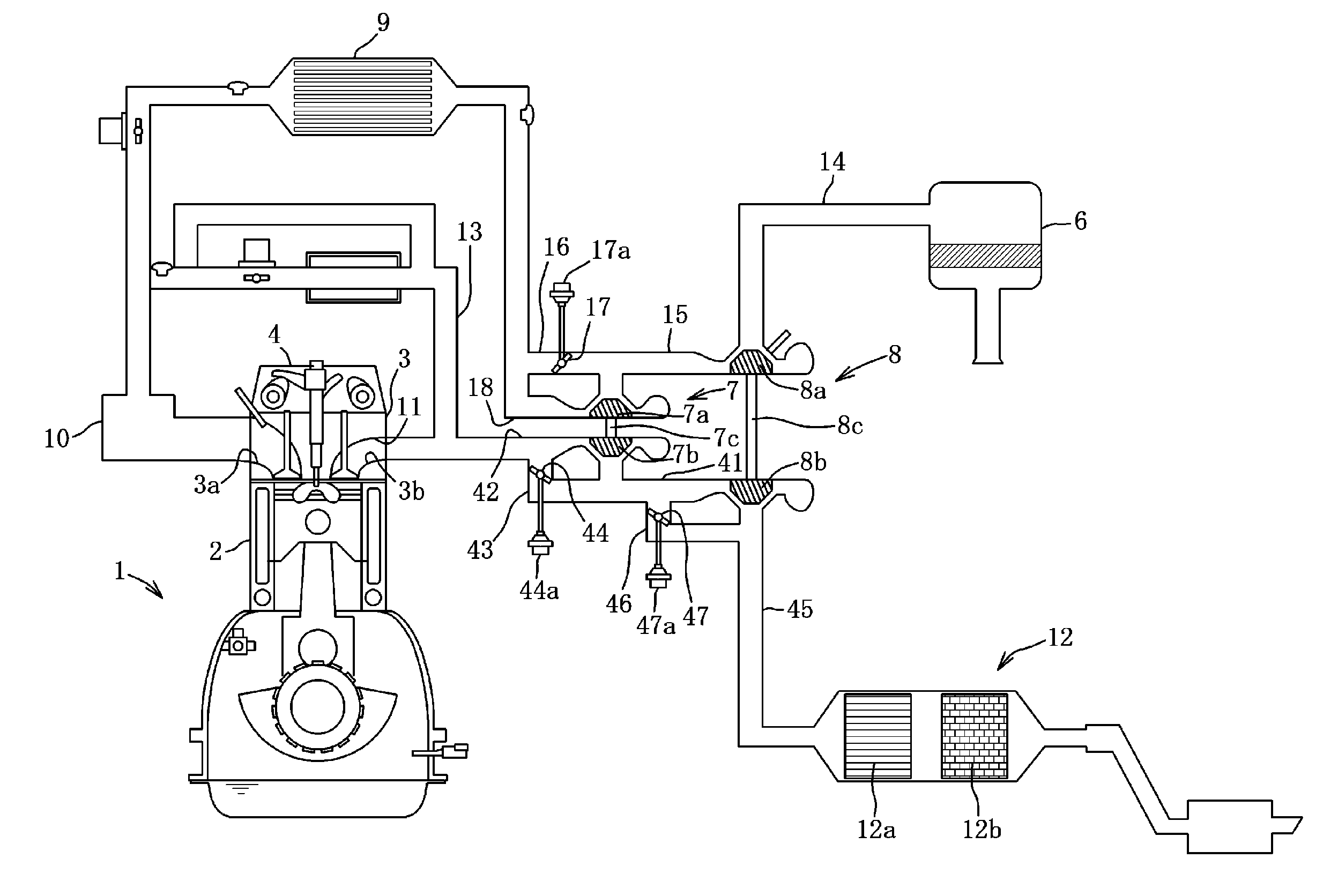
[0013]According to an embodiment of the present invention, a
turbine shaft of the first turbocharger and a
turbine shaft of the second turbocharger are arranged substantially in parallel to each other, an exhaust-gas purification device is arranged on the side of one end of the
turbine shaft, both the return passages of the first and second turbochargers are arranged on the side of the other end of the turbine shaft relative to the exhaust-gas purification device in an axial direction of the turbine shaft, and the return passage of the first turbocharger is arranged on the side of the other end of the turbine shaft relative to the return passage of the second turbocharger in the axial direction of the turbine shaft. Thereby, since the
metal-made return passage of the second turbocharger is provided between the exhaust-gas purification device and the flexible hose and the distance between the exhaust-gas purification device and the flexible hose can be greater, the heat damage of the flexible hose by the exhaust-gas purification device can be restrained, so that the appropriate oil return of the first and second turbochargers can be secured.
[0014]According to another embodiment of the present invention, the exhaust-gas purification device is a
diesel particulate filter. Thereby, even if the DPF (
Diesel Particulate Filter) which tends to generate heat greatly is provided, the heat damage of the flexible hose can be restrained, so that the appropriate oil return of the first and second turbochargers can be secured.
[0015]According to another embodiment of the present invention, the first turbocharger is a turbocharger to operate at a low engine-speed, and the second turbocharger is a turbocharger which operates at a middle and high engine-speed. Thereby, the vibration move of the second turbocharger having the higher turbine speed can be absorbed by the long metal-made return passage of the second turbocharger which is equipped with the
bellows-shaped
vibration absorption portion, so that the reliability of the return passage of the second turbocharger can be secured.
[0016]According to another embodiment of the present invention, the lubricating oil supplied from the engine is supplied to an oil distributer from an oil gallery of a
cylinder head, and then to the shaft bearing portions of the first and second turbochargers. Thereby, since the number of an oil take-out portion as the engine-side connection portion can be less than that of supply passages of the first and second turbochargers, the supply passages of the first and second turbochargers can be connected to the engine side wall compactly by using a smaller layout space, so that the layout flexibility around the engine can be increased.

