[0052]The foregoing and other advantages and features will be more fully understood from the following detailed description of an embodiment with reference to the accompanying drawings, to be taken in an illustrative and not limitative, in which:
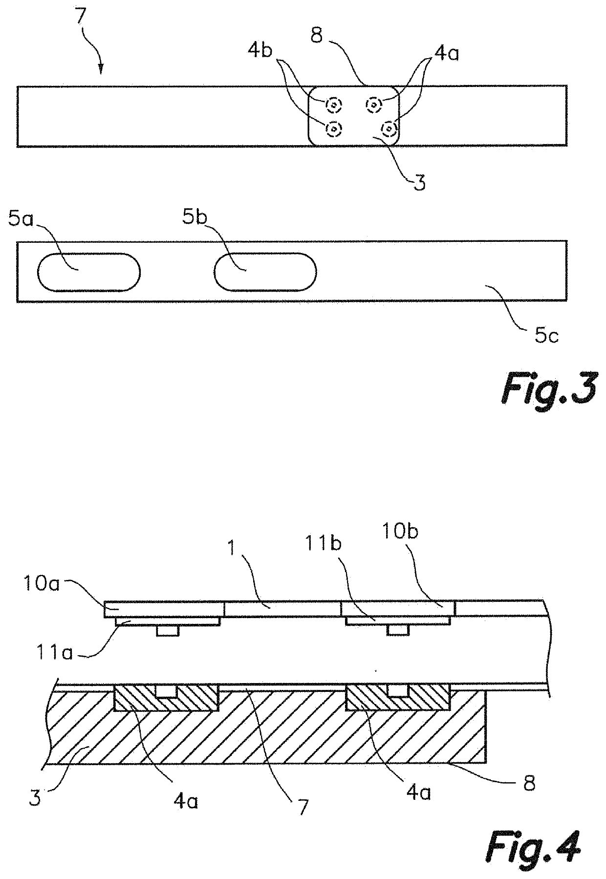
[0053]FIG. 1 illustrates a perspective view, of one possible embodiment, of the different elements that comprise the wearable thoracic element in the form of a band although, the casing 8 containing the processing unit 3 and the terminals 4a and 4b, where the first sensor 1 and the second sensor 2 are connected, are not shown as they are positioned on the front side of the covering layer 7.
[0054]The first sensor 1, which is a laminated strain gauge, must be located on an elastic portion 5c of the support layer 5, if said support layer 5 is made up of several materials and not all of them are elastic and therefore there are different portions which comprise the support layer 5.
[0055]That is why, in order for the first sensor 1 to be able to expand and contract accordingly when the individual wearing the thoracic band inhales and exhales, allowing said first sensor 1 to detect the breathing rate of said individual, it must be located on an elastic portion 5c of the support layer.
[0056]According to a preferred embodiment, the support layer 5 is elastic throughout all its extension and the first sensor 1 of the wearable thoracic band is made up of two parallel extended strips 1a and 1b with a connector 11a and 11b placed on connecting tabs, 10a and 10b respectively, at the end of each strip, 1a and 1b respectively, wherein one of the strips 1a is longer than the other strip 1b and both strips 1a, 1b are joined together at one end distal from said connectors 11a and 11b and said linear strips 1a, 1b are part of a single entity.
[0057]The second sensor 2 is formed by a first ECG laminated electro-conductive element 2a and a second ECG laminated electro-conductive element 2b each of them provided with connectors 21a and 21b situated on connecting tabs, 20a and 20b respectively, at two adjacent ends, wherein the first 2a and second 2b ECG electro-conductive elements are superimposed but separated by an electric insulating rigid laminar layer 6, and the support layer 5 comprising a first opening 5a and a second opening 5b at a given distance, through which a portion of said electro-conductive elements 2a and 2b are exposed so they are able to be in contact, as pads, directly with the skin of the individual on the interior side of the support layer 5.
[0058]In order to improve the contact between the pads formed by electro-conductive elements 2a and 2b of the second sensor 2 and the individual, the pads may include membranes which absorb the individuals' perspiration as well as specialised hydrogel membranes which also improve the electro-conductive elements 2a and 2b contact.
[0059]The materials used for both the first 1 and second 2 sensors must be electrically conductive and at least the first sensor 1 must have good elasticity properties.
[0060]The materials used for the different layers 5 and 7 of the thoracic band are elastic albeit, they are not required to have the same properties or be the same elastic material and therefore, the positioning of the first and second sensors, 1 and 2 respectively, is irrelevant as long as they are adjacent to each other and on the same side of the support layer 5.
[0061]According to one embodiment, the covering layer 7 only covers the laminated sensors 1 and 2 although, in a preferred embodiment, the covering layer 7 covers the whole extension of the support layer 5 wherein said covering layer 7 also acts as an embellishment for the thoracic band.
[0062]FIG. 2 illustrates a front view of the wearable thoracic band where we can clearly observe the placement of the sensors 1 and 2 and the different layers 5, 6 and 7 that comprise the thoracic band. The casing 8 which includes the processing unit 3 and the terminals 4a and 4b for the first 1 and second 2 sensor respectively is not represented in this figure in order to simplify it.
[0063]According to one embodiment, the first sensor 1 and the second sensor 2 are situated on the front side of the support layer 5, as the rear side is in direct contact with the individual, and they are covered by the covering layer 7 wherein said covering layer 7 may cover the whole extension of the support layer 5 or only those portions of the support layer (5) where the first and second sensors 1 and 2 are placed.
[0064]The first sensor 1 is a strain gauge and the second sensor 2 is formed by the first laminated ECG electro-conductive element 2a and the second laminated ECG electro-conductive element 2b.
[0065]The support layer 5 has two openings: the first opening 5a through which the first laminated ECG electro-conductive element 2a is exposed and the second opening 5b through which the second laminated ECG electro-conductive element 2b is exposed. The shape of the openings 5a and 5b may be any shape known in the state of the art which allows an adequate contact between the electro-conductive elements 2a and 2b and the individual. The opening of the support layer 5 may also be formed by a single opening instead of multiple openings, as shown in this particular embodiment of the thoracic band.
[0066]Placed in between the first and second laminated ECG electro-conductive elements 2a and 2b is the electric insulating rigid laminar layer 6.
[0067]The connectors 11a, 11b, 21a and 21b are placed at the end of connecting tabs 10a, 10b, 20a and 20b of both sensors 1 and 2 respectively located in proximity to each other with the connectors facing the terminals 4a and 4b located on the covering layer 7 relative to the position of the casing 8.
[0068]FIG. 3 illustrates a detailed view of the front of the covering layer 7 and the rear side of the support layer 5 in a preferred embodiment of the wearable thoracic band.
[0069]The front view of the covering layer (7) shows the disposition of the casing 8 wherein said casing 8 contains the processing unit 3 and is situated on the external (or front) side of the covering layer 7 of the thoracic band.
[0070]In a preferred embodiment, the casing 8 contains two terminals 4a for the first sensor 1 and its respective connectors 11a and 11b and two terminals 4b for the second sensor 2 and its respective connectors 21a and 21b wherein, the terminals 4a and 4b are located in proximity to each other.
[0071]The casing (8) should cover said terminals 4a and 4b of both the first 1 and second sensor 2, respectively, but the terminals 4a and 4b have been represented in order to visualize how they are positioned.
[0072]The rear view of the support layer 5, allows us to see the disposition of the first opening 5a relative to the first electro-conductive element 2a and the disposition of the second opening 5b relative to the second electro-conductive element 2b of the second sensor 2.
[0073]FIG. 4 illustrates an enlarged detailed view of the connection between the connectors 11a and 11b of the first sensor 1 and their respective terminals 4a situated on the casing 8. This detailed view of the connectors' arrangement between the first sensor 1 and the terminals 4a of the casing 8 is applicable to the connection of the second sensor 2 to the terminals 4b of the casing 8.
[0074]The first connector 11a placed on the connecting tab 10a relative to the extended strip 1a and the second connector 11b placed on the connecting tab 10b relative to the extended strip 1b are connected to the terminals 4a situated on the casing 8.
[0075]The two extended strips 1a and 1b are parallel and wherein the extended strip 1a is longer than the extended strip 1b corresponding to the first sensor 1 which is a laminated strain gauge.
[0076]In the case of the second sensor 2, the first connector 21a is situated on the connecting tab 20a relative to the first electro-conductive element 2a and the second connector 21b is situated on the connecting tab 20b relative to the second electro-conductive element (2b) which are connected to the terminals 4b situated on the casing 8 and wherein the terminals 4b are positioned on the same vertical axis.
[0077]The electric insulating rigid laminar layer 6 is placed in between the first and second electro-conductive elements 2a and 2b of the second sensor 2.
[0078]In a preferred embodiment of the wearable thoracic band, the connectors 11a, 11b, 21a and 21b and the terminals 4a and 4b are snap connectors.
[0079]It will be understood that various parts of one embodiment of the invention can be freely combined with parts described in other embodiments, even being said combination not explicitly described, provided there is no harm in such combination. Thus, the wearable thoracic element, in the form of a band previously disclosed, may be integrated into any kind of garment or textile fabric which can then be integrated into a garment or used independently.