Head plate provided for an operating table and adjustable with one hand

a technology of head plates and operating tables, which is applied in the field of multi-part displaceable head plates for operating tables, can solve the problems of pivot joint blocking mechanisms, negative impact on the rigidity of the head plates under load, and unknown two-part head plates, etc., and achieves the effect of safe and convenient handling

Active Publication Date: 2020-11-05
MAQUET GMBH
View PDF0 Cites 1 Cited by
  • Summary
  • Abstract
  • Description
  • Claims
  • Application Information

AI Technical Summary

Benefits of technology

[0016]The disclosure is therefore based on the object of specifying a multi-part displaceable head plate for fastening to an operating table, with which the adjustment of the desired position of the head plate segments can be handled safely and conveniently by one single user.

Problems solved by technology

However, such solutions are not known for two-part head plates.
Due to the size of the gas springs, head plates are predominantly made with gas springs attached on one side, which has a negative impact on the rigidity of the head plates under load.
Basically, however, pivot joint blocking mechanisms, which are implemented with coupling gears and latchable thrust joints, are restricted to the extent that the adjustable angular range is restricted due to occurring dead center positions.
Experience has shown, however, that the operation and synchronization of different blocking mechanisms on a head plate are difficult.
When using several manually operated blocking and locking mechanisms, a confusion of the respective control units cannot be ruled out, so that there is a risk of unintentional unlocking of a joint during an operation.
Solutions with several individually operated blocking mechanisms are also ergonomically disadvantageous.
Such a design of the unlocking mechanism is structurally very complex and not torsion-proof.
In addition, it requires an increased effort due to the increased friction and leverage, as well as complex assembly and adjustment.
This no longer leaves a hand free to support the patient's head and protect it from uncontrolled movements.
A sensitive positioning of the patient's head is therefore only possible to a limited extent during an operation by an individual user.
Furthermore, when pivoting the head plate 1′ already known from the prior art, there is a risk for the user of jamming his hands between the frame 7′, the carrier plate 8′ and a lateral standard rail 6′.

Method used


Image

  • Head plate provided for an operating table and adjustable with one hand
  • Head plate provided for an operating table and adjustable with one hand
  • Head plate provided for an operating table and adjustable with one hand

Examples


Embodiment Construction

[0065]In the following description, exemplary embodiments of the present disclosure are described with reference to the drawings. The drawings are not necessarily to scale, but are only intended to illustrate the respective features schematically.

[0066]It should be noted that the features and components described below can each be combined with one another, regardless of whether they have been described in connection with a single embodiment. The combination of features in the respective embodiments merely serves to illustrate the basic structure and the mode of operation of the claimed device.

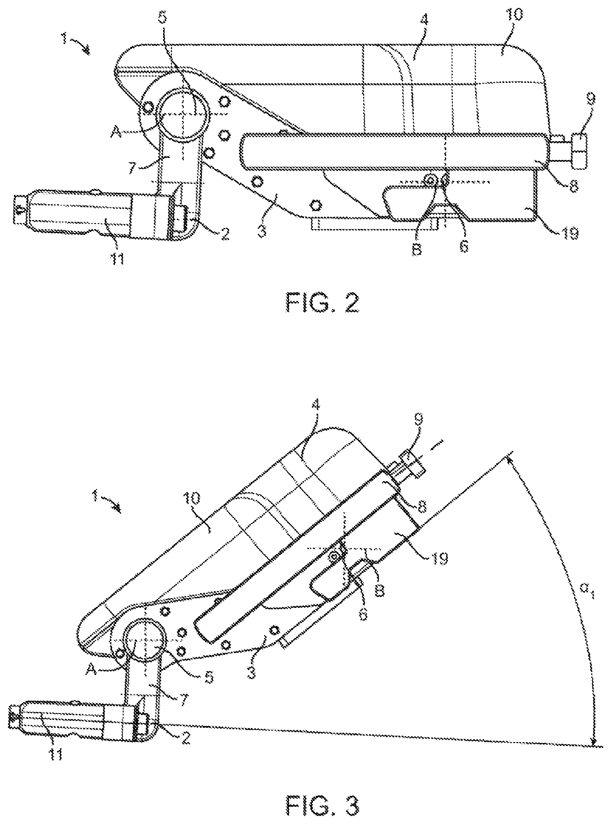
[0067]FIG. 2 is a side view showing a multi-part head plate 1 according to the disclosure as an embodiment. The head plate 1 serves to support the head of a patient lying on an operating table 30 (see FIG. 6) during an operation.

[0068]As shown in FIG. 2, the head plate 1 comprises a coupling arrangement 2 for coupling to the operating table and two head plate segments 3 and 4. In this case, a ...


PUM


Abstract

Multi-part displaceable head plate (1) for an operating table (30), comprising: a coupling arrangement (2), a positioning segment (3) for positioning the head plate (1), a head support segment (4) for supporting the head of the patient, and an unlocking device (24) for unlocking two joint arrangements (5), (6).
The positioning segment (3) and the head support segment (4) are each pivotably connected to the coupling arrangement (2) and to the positioning segment (3), via a first (5) and a second (6) joint arrangement respectively.

Description

BACKGROUND OF THE DISCLOSURE[0001]The disclosure relates to a multi-part displaceable head plate for an operating table according to the preamble of claim 1.[0002]During an operation, a patient is lying on his back, stomach or side on an operating table. His head can be supported by a head plate attached to the operating table.[0003]Immediately before some operations, the patient must be anesthetized and connected to a ventilator. For this purpose, an anesthetist has to stretch the head of the patient positioned in a supine position for intubation. This can be achieved by folding the head plate down. In order to position the patient's head as gently as possible, the anesthetist should support the head in the area of the neck with one hand, while unlocking, adjusting the angle and securely fixing the head plate with his free hand.[0004]In particular in the case of neurosurgical interventions, in which the position of the head has to be positioned and fixed several times in a targeted...

Claims


Application Information

Patent Timeline
Patent Type & Authority Applications(United States)
IPC IPC(8): A61G13/12A61G13/08
CPCA61G13/08A61G13/121A61G2200/327A61G7/072A61G13/101A61G13/1295A61G2200/32A61G2203/70
Inventor KATZENSTEIN, BERNHARDGAISER, IMMANUELSCHRÖTER, JENSDEL ALCAZAR VON BUCHWALD, RODRIGOKRICKEBERG, THOMAS
Owner MAQUET GMBH
Why Eureka
Try Eureka