Truckle structure and cabinet

a truckle and structure technology, applied in the field of trucks, can solve the problems of insufficient structural strength/rigidity of the whole cabinet frame, may swing to a certain extent under an external force, and the existing stand columns are simple and slim in structure, so as to achieve firmer and more durable

Pending Publication Date: 2020-11-05
ZHEJIANG SHIP ELECTRONICS TECH
View PDF0 Cites 2 Cited by
  • Summary
  • Abstract
  • Description
  • Claims
  • Application Information

AI Technical Summary

Benefits of technology

The present invention provides a truckle structure and cabinet that are mounted on the ground, providing a more durable and secure mounting solution. The truckle structure is compact and stable, allowing for direct mounting on the ground and easy transportation without the need for support legs or costly mounting costs. The support structure is composed of a triangular support that is connected to the truckle in an articulated manner, ensuring stable support and preventing rotation in the same direction. The cabinet frame is stronger and more stable, with a layout optimized for better stability and more convenient and flexible cable arrangement. The truckle structures are mounted at the corners of the cabinet frame, providing optimal mounting convenience, firmness, and reliability.

Problems solved by technology

However, after the cross beams are mounted on the cabinet frames, due to limitation of an inserted connection manner or a splicing connection manner, the whole cabinet frames still have insufficient support strength / structural rigidity and may swing to a certain extent under an external force.
In addition, existing stand columns are simple and slim in structure, and have insufficient structural strength and rigidity; after the cross beams are additionally mounted in the middle of sides of the cabinets, cable arrangement in the whole cabinets will be influenced; and the cross beams may also influence the installation and layout of cable arrangement structures and obstruct device channels.
Furthermore, existing cabinets mounted with common truckles capable of moving freely cannot be directly transported or used, wooden pallets need to be additionally used during transportation of the existing cabinets, and support legs need to be additionally used when the existing cabinets are used by customers.
Most cabinets on the present market are additionally mounted, near the truckles, with the support legs required to be directly fixed to the cabinets to guarantee a fixing effect, and in this case, the support legs fail to be closely connected to the truckles.
Consequentially, the firmness is not good.

Method used


Image

  • Truckle structure and cabinet
  • Truckle structure and cabinet
  • Truckle structure and cabinet

Examples


Embodiment Construction

[0043]The technical solution of the present invention is further expounded below with reference to the specific embodiments and accompanying drawings, and the following embodiments are not intended to limit the present invention.

[0044]The technical solution of the present invention is expounded below with reference to FIG. 1 to FIG. 11.

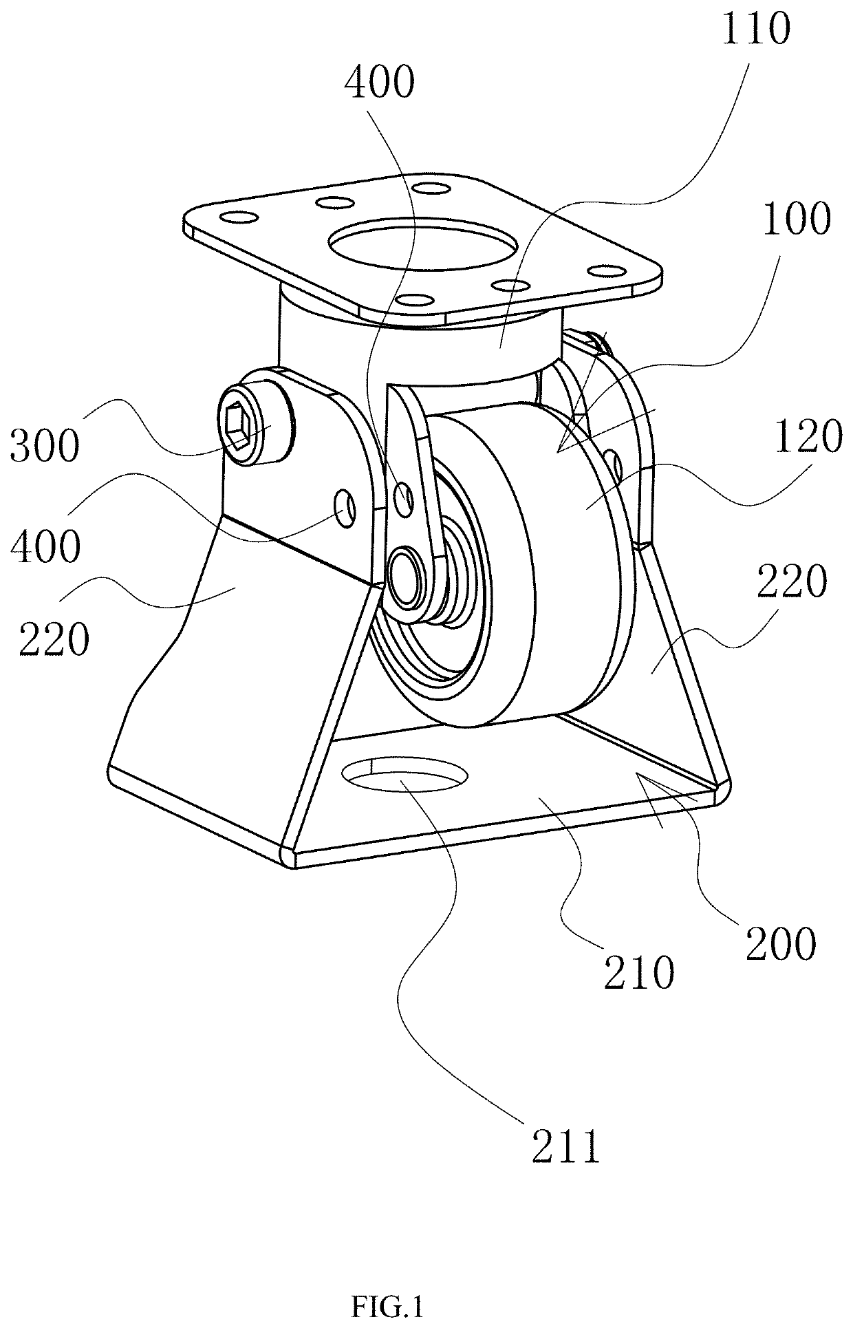
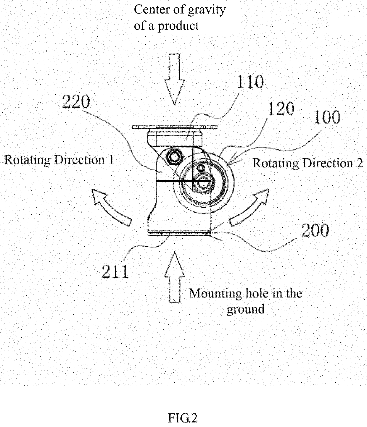
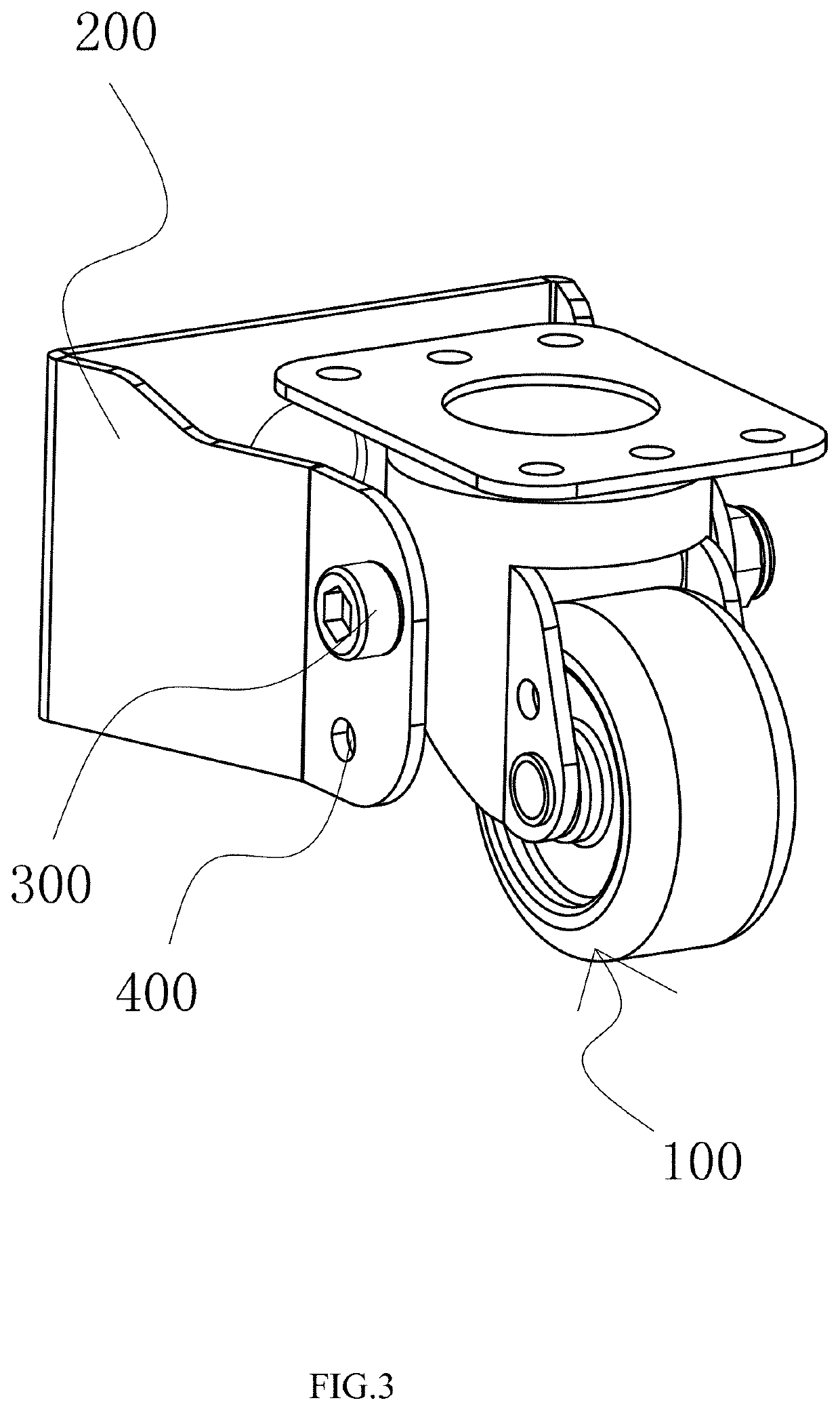
[0045]As shown in FIG. 1 to FIG. 6, a truckle structure comprises:

[0046]A truckle 100 including a mounting base 110 and a wheel 120 which is rotatably mounted on the mounting base 110 and is preferably located below the mounting base 110;

[0047]A support 200 located outside the wheel 120 and compose of a mounting portion 210 located at a lower position as well as two connecting portions 220 respectively located on two sides of the mounting portion 210, wherein the two connecting portions 220 are formed in a manner that the left side and right side of the mounting portion 210 are upwards bent towards the middle, the support 200 is rotatably connected to...


PUM


Abstract

Provided are a truckle structure and a cabinet. The truckle structure comprises: a truckle and a support, wherein the truckle includes a mounting base and a wheel rotatably mounted on the mounting base; the support is composed of a mounting portion located at a lower middle position as well as two connecting portions respectively located on two sides of the mounting portion; the two connecting portions are formed in a manner that the left side and the right side of the mounting portion are upwards bent towards the middle, the support is rotatably connected to the mounting base through the two connecting portions, and the mounting base is located between the two connecting portions; and a mounting hole is formed in the mounting portion, center of the mounting hole and center of gravity of the truckle are on a same straight line, and center of gravity of the support deviates from the straight line. The truckle structure can be directly mounted on the ground and is firmer and more durable.

Description

BACKGROUND OF THE INVENTION1. Technical Field[0001]The present invention belongs to the technical field of cabinets, and relates to a truckle structure and a cabinet.2. Description of Related Art[0002]With the rapid development of digital construction, cabinets, as important data communication processing devices, have been widely applied to the fields of communication, network data processing, and the like.[0003]Frames of the cabinets on the present market are simply designed in structure and are directly formed by splicing thin profiles. Most profiles spliced among a top frame, a bottom frame, and stand columns are connected in an insertion manner. For example, the profiles are directly inserted into the top frame, the bottom frame, and the stand columns, or are connected to the top frame, the bottom frame, and the stand columns through tee joints. In this case, it is necessary to mount cross beams between every two stand columns to guarantee the support strength of the whole cabin...

Claims


Application Information

Patent Timeline
IPC IPC(8): B60B33/06B60B33/00
CPCB60B33/06B60B33/0028H05K7/18B60B33/0089B60B33/04
Inventor LI, YONGPINGLUO, XIANWEI
Owner ZHEJIANG SHIP ELECTRONICS TECH
Why Eureka
Try Eureka