Low profile magnetoresistive imaging sensor array

a low-profile magnetoresistive and imaging sensor technology, applied in the field of currency detection, magnetic read head, imaging, can solve the problems of limited fidelity of magnetically printed images, insufficient scanning quality, low current scanning speed, etc., and achieve the effect of reducing the distance between the medium and the imaging sensor array and reducing the spacing

Active Publication Date: 2017-01-05
MULTIDIMENSION TECH CO LTD
View PDF3 Cites 2 Cited by
  • Summary
  • Abstract
  • Description
  • Claims
  • Application Information

AI Technical Summary

Benefits of technology

[0007]As for the problem in the prior art of a large spacing between a magnetoresistive imaging sensor array and a medium, the technical solution provided by the present invention to reduce the spacing between the magnetoresistive imaging sensor array and the medium includes: optimizing the arrangement of an application integrated circuit and a magnetoresistive imaging sensing element array, mounting an integrated circuit on a top surface and a bottom surface of a sensing element array substrate and on a top surface and a bottom surface of an ASIC substrate separately, and using the through-the-chip interconnections and other technologies that can reduce the spacing between the magnetoresist

Problems solved by technology

However, with rapid development of reduction printing and scanning technologies, there is a need and an opportunity to read printed matters smaller than 25 μm, and moreover, the existing digital scanning speed is not high and the scanning quality is not good enough.
Therefore, a magnetic scanning head with higher spatial resolution is really needed, a magnetic scanning system capable of providing a magnetically printed image of high fidelity is also needed, and the fidelity of

Method used


Image

  • Low profile magnetoresistive imaging sensor array
  • Low profile magnetoresistive imaging sensor array
  • Low profile magnetoresistive imaging sensor array

Examples


Embodiment Construction

[0042]The present invention is described in detail below with reference to embodiments and the accompanying drawings.

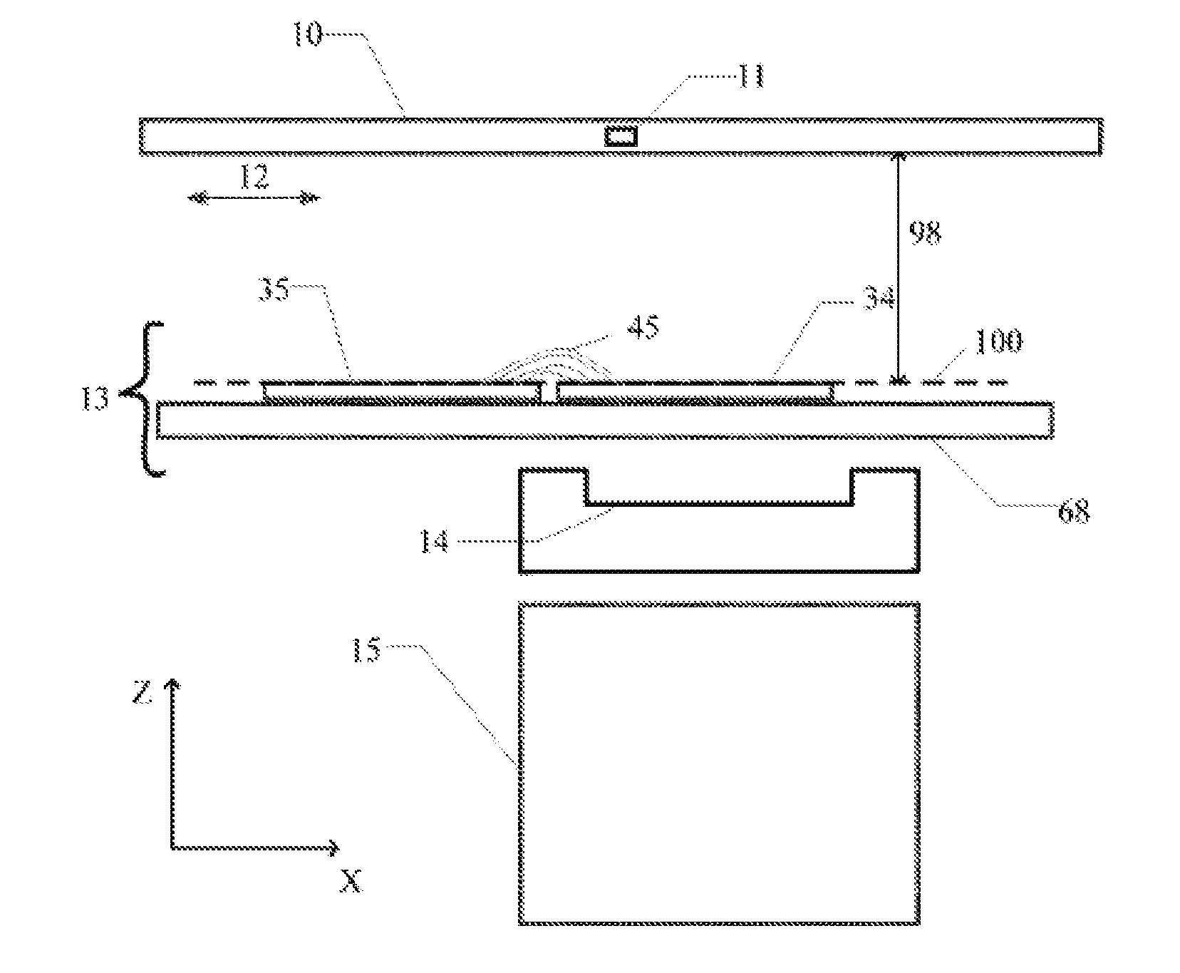
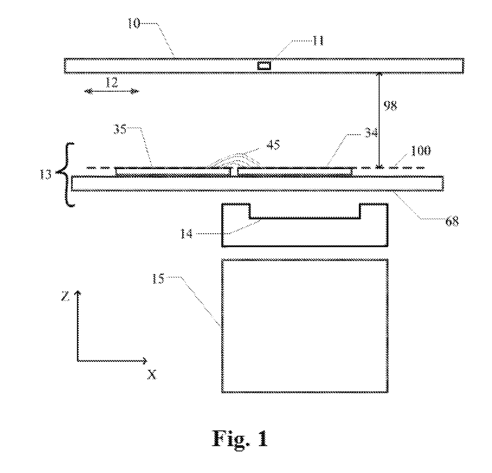
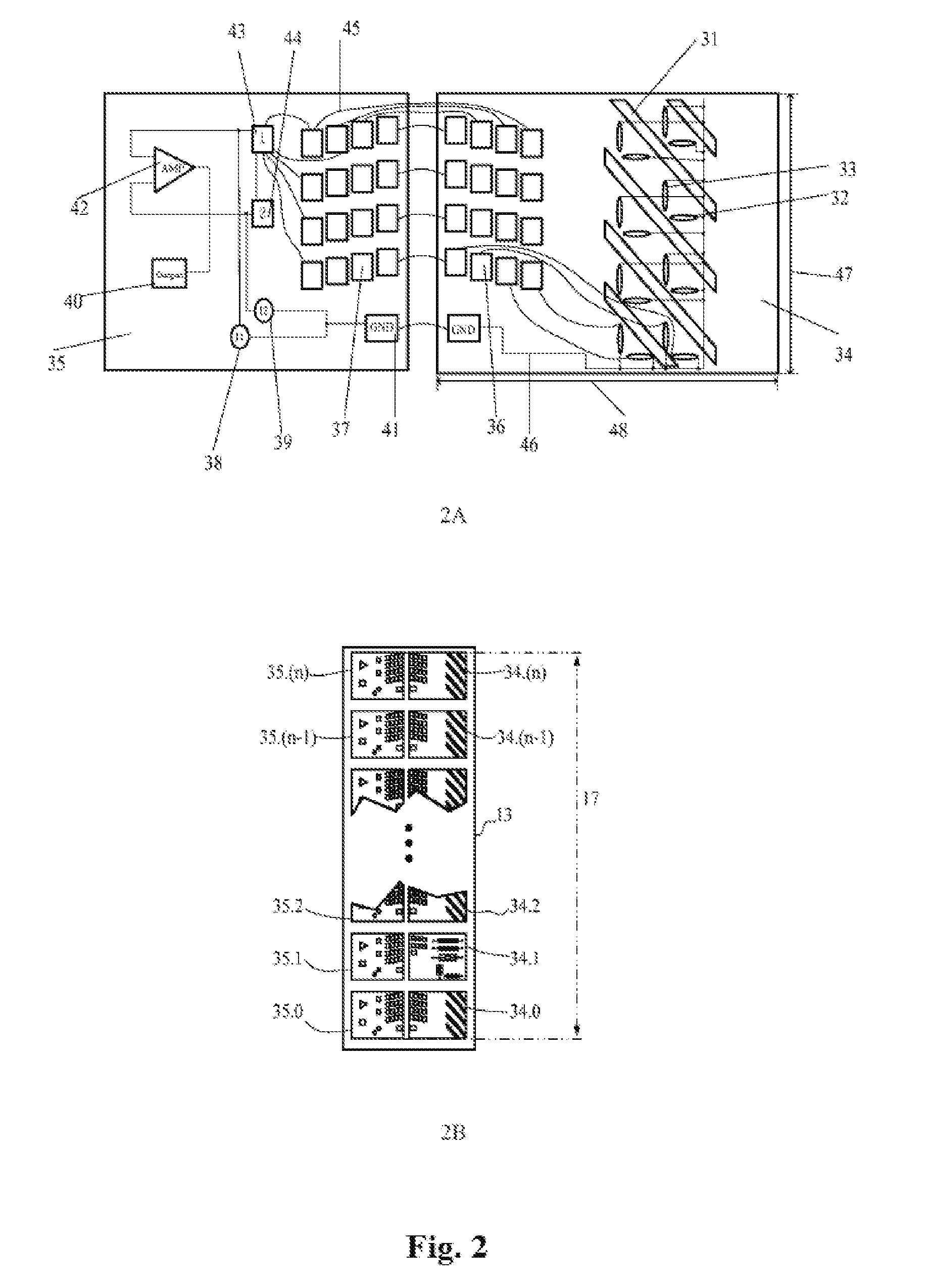
[0043]FIG. 1 and FIG. 2 show a magnetoresistive imaging sensor array in the prior art and the defect thereof as well as basic knowledges for designing and using the magnetoresistive imaging sensor array. The description about the design of the low profile magnetoresistive imaging sensor array in the present invention starts from FIG. 3. Specifically, the magnetoresistive imaging sensor array is a magnetic medium scanning head. FIG. 1 shows a medium 10 passing through the sensor array 13, where the medium 10 may be an entire bill or an entire piece of paper moving along an axial medium moving direction 12, and this axis is parallel to an X-axis 1. A standard coordinate system is shown in the lower right corner of FIG. 1, and the coordinate system has the X-axis 1, a Y-axis 2 (along a paper inward direction) and a Z-axis 3. A common motor and / or roller is used to drive ...


PUM


Abstract

A low profile magnetoresistive imaging sensor array based on the principle of magnetic induction, which reduces a distance between a medium imaging sensor array and a medium by optimizing the arrangement of an application integrated circuit and a sensing element array and using an electric connection technology which can reduce the distance between the medium imaging sensor array and the medium, thereby increasing the resolution of the existing medium imaging sensor. The low profile magnetoresistive imaging sensor array comprises a sensing element array and an application integrated circuit, and also comprises a circuit which provides a power for the sensing element array, a magnetoresistive sensing element array selection circuit, a signal amplification circuit, a digitizer, a memory circuit, and a microprocessor. Additionally, the sensing element array comprises at least one magnetoresistive sensing element.

Description

TECHNICAL FIELD[0001]The present invention relates to the technical fields of currency detection, magnetic read heads, imaging and the like, and in particular, to a low profile magnetoresistive imaging sensor array and chip-level packaging.BACKGROUND ART[0002]The maximum diameter of a physical area for high-resolution dotting on paper is 25 μm. An electronic image detector reads such a minute image from a medium and converts the image into an electric signal which is generally in a digital data format, and then the image or data can be displayed on a screen or be replicated.[0003]Reduction printing is mainly used in the fields of banknote printing, photocopying, watermarking and paper document security. These fields have different sensing requirements because data can be presented in various formats, for example, using magnetic ink or optical ink. Besides, the printing format is scarcely limited, and a printed character or target may appear at any position of a medium, may have any ...

Claims


Application Information

Patent Timeline
IPC IPC(8): G01R33/09G06K9/20G06K9/18G01R33/07G06V30/224
CPCG01R33/09G06V30/2253G01R33/072G01R33/091
Inventor TONDRA, MARK C.XUE, SONGSHENGDEAK, JAMES GEZAJIN, INSIKSHEN, WEIFENG
Owner MULTIDIMENSION TECH CO LTD
Why Eureka
Try Eureka