

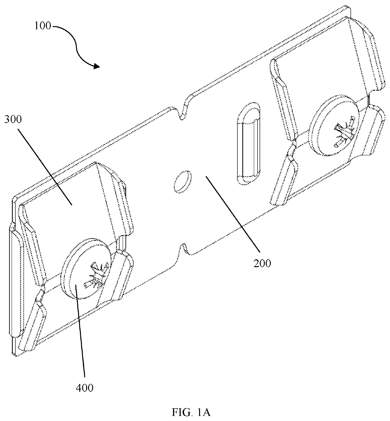
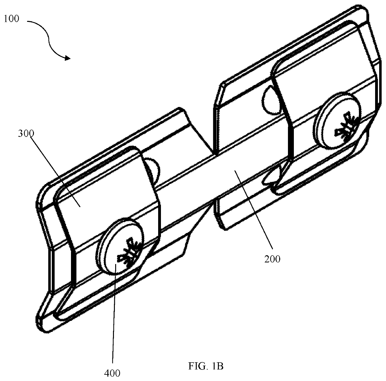
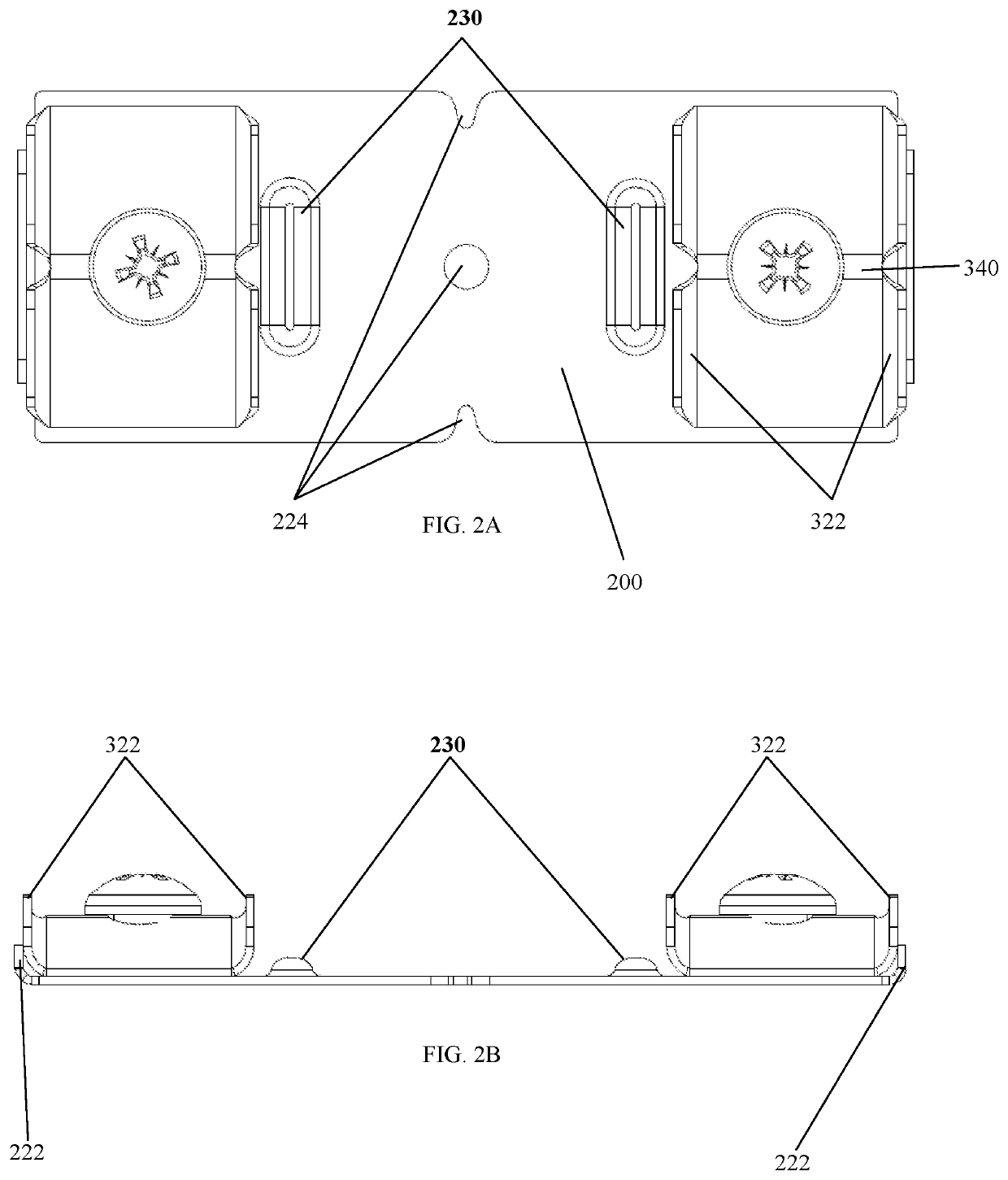
Splice plate with a cam lock
a cam lock and splice plate technology, applied in the field of splice plates, can solve the problems that the cam lock or the base plate material may be harder than aluminum, and achieve the effects of avoiding face distortion, reducing the possibility of trim separation, and increasing construction efficiency
- Summary
- Abstract
- Description
- Claims
- Application Information
AI Technical Summary
Benefits of technology
Problems solved by technology
Method used
Image

Examples
Embodiment Construction
[0055]The features and benefits of the disclosed splice plate 100 are illustrated and described by reference to exemplary embodiments. The disclosure also includes the drawing, in which like reference numbers refer to like elements throughout the various figures that comprise the drawing. This description of exemplary embodiments is intended to be read in connection with the accompanying drawing, which is to be considered part of the entire written description. Accordingly, the disclosure expressly should not be limited to such exemplary embodiments illustrating some possible non-limiting combination of features that may exist alone or in other combinations of features.
[0056]In the description of embodiments, any reference to direction or orientation is merely intended for convenience of description and is not intended in any way to limit the scope of the present invention. Relative terms such as “lower,”“upper,”“horizontal,”“vertical,”“above,”“below,”“up,”“down,”“top,” and “bottom”...
PUM
 Abstract
Description
Claims
Application Information