Improvements to flexible straw with control means for use with a drinking vessel

Pending Publication Date: 2020-11-12
AR DESIGN CONSULTING LTD
View PDF1 Cites 1 Cited by
  • Summary
  • Abstract
  • Description
  • Claims
  • Application Information

AI Technical Summary

Benefits of technology

[0101]In another aspect, the system comprises of a unitary drinking tube component. It is an object of the present invention to provide a flexible, unitary, drinking tube construction for a drinking vessel, in which an upper proximal straw portion is removably and frictionally connected and secured to a drinking vessel lid in which the drinking tube valve means is integrally moulded to a lower distal end of the flexible drinking tube. Since the valve is incorporated into the flexible drin

Problems solved by technology

However, rigid straws tend to be too rigid to bend effectively and so tend to be unsuitable for the user.
A major disadvantage of such valves in the art is that, due to the complex construction, they are often difficult to assemble and disassemble for regular cleaning, and thereby can suffer damage.
As the valve can be damaged during the assembly or disassembly process, the non-spill and hygienic properties of the valve cannot be ensured.
Valves known in the art are also more costly to manufacture due to their complex construction.
Another disadvantage of current flexible straws with integrated valves is that the cross-sectional dimensions of the straw valve designs used can be quite small as the valves are often incorporated within the through bore

Method used


Image

  • Improvements to flexible straw with control means for use with a drinking vessel
  • Improvements to flexible straw with control means for use with a drinking vessel
  • Improvements to flexible straw with control means for use with a drinking vessel

Examples


Embodiment Construction

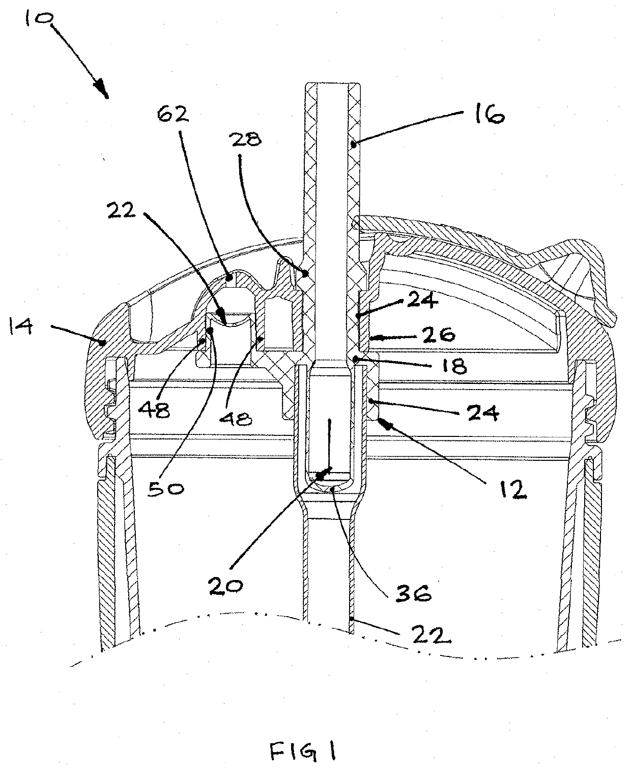
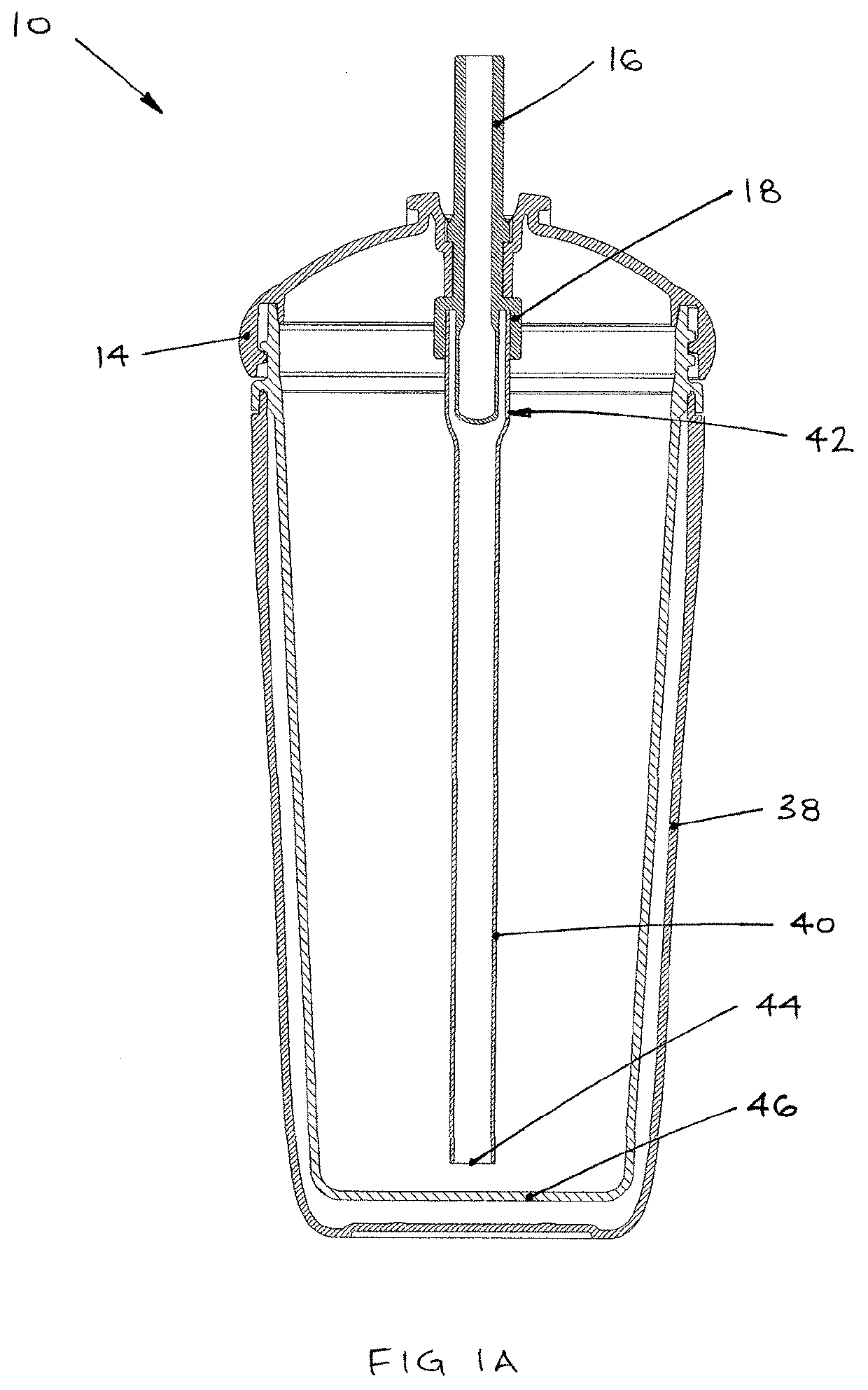
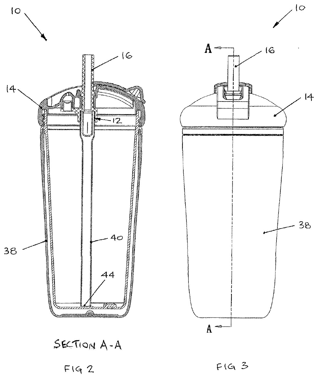
[0144]Referring now to FIG. 1, a non-spill drinking cup system 10 includes a drinking tube 12 and a lid assembly 14.

[0145]The drinking tube 12 includes a generally tubular drinking straw portion 16 protruding from an intervening portion 18. The drinking tube 12 also includes a drinking valve portion 20 and a venting valve 22. In the depicted embodiment, the generally tubular drinking straw portion 16, intervening portion 18, drinking valve portion 20 and venting valve 22 are integrally moulded to form the drinking tube 12. The drinking tube 12 is removably attached to the underside of the lid assembly 14 and is capable of providing full fluid flow through the flexible drinking straw portion 16 even under low suction. The drinking tube 12 is described in more detail with respect to FIGS. 4-14.

[0146]The lid assembly 14, as shown in FIGS. 1 and 21-24, includes a locating hole or aperture 24 which protrudes from the underside of the lid assembly 14 to define a first locating boss 26 (se...


PUM


Abstract

A non-spill drinking cup system includes a container; a lid assembly that is removably attachable to the container, comprising an aperture; and a drinking tube, wherein the drinking tube extends through the aperture, the drinking tube including an open end, a closed end, and a side wall; and a drinking valve, wherein the drinking valve includes at least one elongate slit disposed within the side wall.

Description

[0001]This invention relates to improvements to a non-spill drinking cup valve system. In particular, the non-spill drinking cup valve system includes a container, a lid assembly and a drinking tube. The drinking tube extends through an aperture located in the lid assembly and also includes an open end, a closed end, and a side wall. A drinking valve is provided as an elongate slit disposed within the side wall of the drinking tube.[0002]More generally, this invention comprises a unitary flexible straw and valve component, designed for ease of drinking by enabling full flow through the valve and flexible straw, whilst maintaining a liquid seal when not in use, thereby preventing accidental spills.INTRODUCTION[0003]Tubular drinking straws used in drinking cups are well known and come in a variety of designs, constructions and materials. They may be simple and inexpensive to manufacture, and include rigid and semi-rigid tubular straws. However, rigid straws tend to be too rigid to ben...

Claims


Application Information

Patent Timeline
IPC IPC(8): A47G19/22A47G21/18B65D47/06B65D47/32B65D51/16
CPCB65D2543/00046A47G21/189B65D47/06A47G19/2266B65D47/32B65D51/16B65D2547/063B65D2205/02
Inventor REES, ARNOLD
Owner AR DESIGN CONSULTING LTD
Why Eureka
Try Eureka