
Method for establishing a signal indicative of the pressure-condition in the as contact-surface befitted rubber-elastic body of a machine foot, as well as machine foot with hydrostatic pressure sensor

Inactive Publication Date: 2020-11-12
NGI AS
View PDF8 Cites 1 Cited by
  • Summary
  • Abstract
  • Description
  • Claims
  • Application Information

AI Technical Summary

Benefits of technology

This patent describes a way to measure the distance between two parts of a rubber-elastic body using a simple and reliable method. By measuring the electrical capacity between two plates, the distance between the two parts can be accurately determined. This helps to ensure optimal adhesion between the rubber and the cap, reducing the likelihood of dirt and bacteria getting inside the machine. The technical effect of this is improved reliability and accuracy in measuring the distance between two parts.

Problems solved by technology

This solution, however, is relatively expensive and also very precise, which is not always necessary.
The load cell contains a strain-gauge embedded in a steel structure and is not a cheap mass-produced product made by the billion.
The machine foot in that document is, however, not suitable to be used in areas where high hygienic requirements apply, among other reasons, due to its complex structure with many visible and exposed components.

Method used


Image

  • Method for establishing a signal indicative of the pressure-condition in the as contact-surface befitted rubber-elastic body of a machine foot, as well as machine foot with hydrostatic pressure sensor
  • Method for establishing a signal indicative of the pressure-condition in the as contact-surface befitted rubber-elastic body of a machine foot, as well as machine foot with hydrostatic pressure sensor
  • Method for establishing a signal indicative of the pressure-condition in the as contact-surface befitted rubber-elastic body of a machine foot, as well as machine foot with hydrostatic pressure sensor

Examples


Embodiment Construction

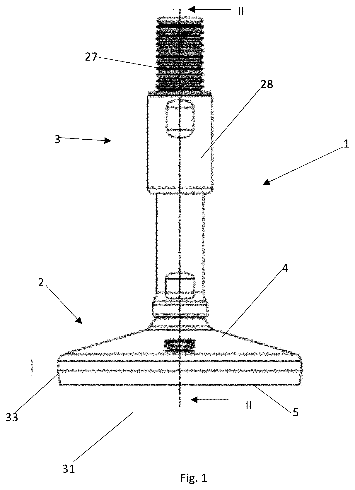
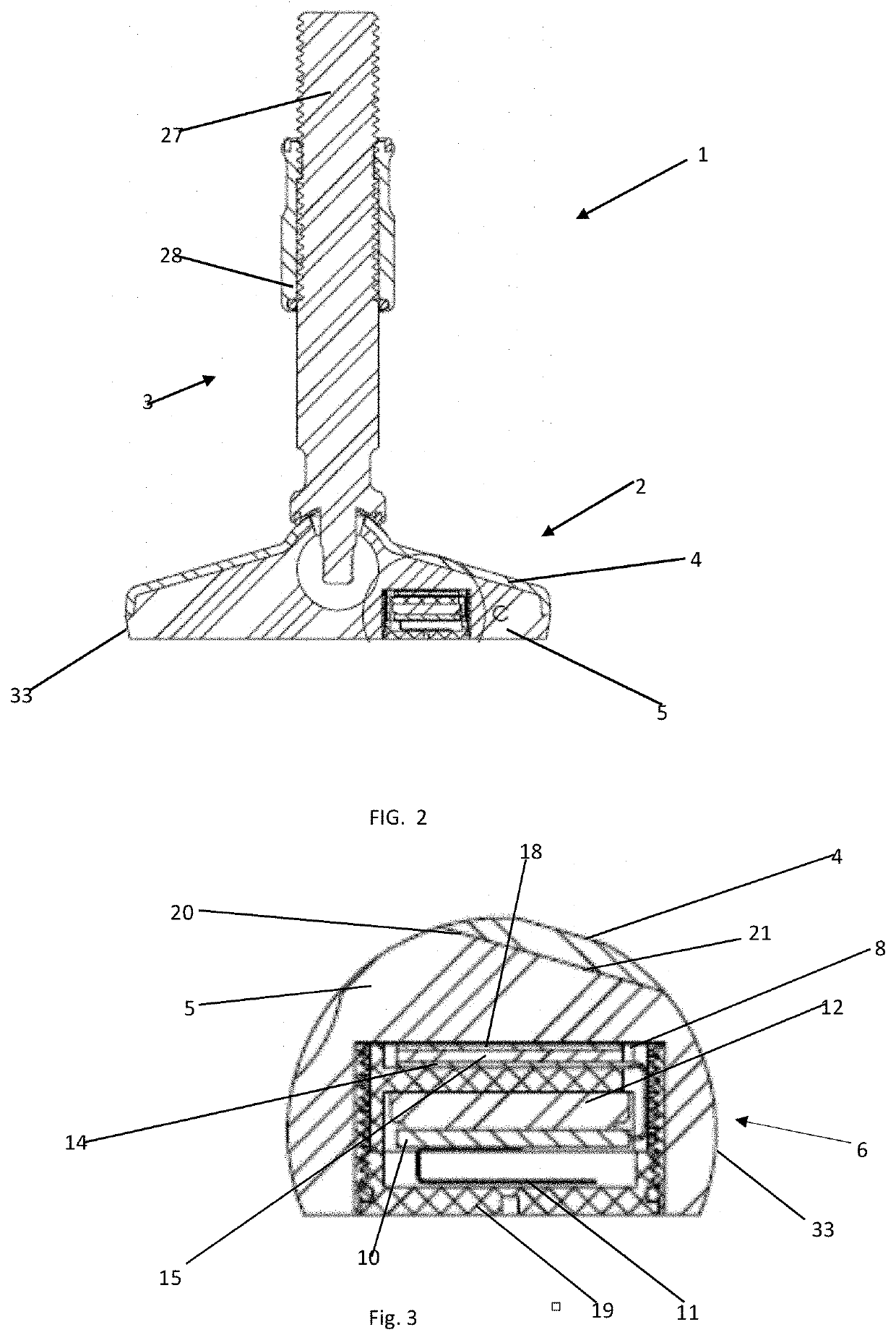
[0110]With reference to FIGS. 1 and 2, leveling block 1 according to the invention will be reviewed.

[0111]Levelling block 1 comprises machine feet. The sensor unit can be used in leveling blocks as well as in machine feet that do not have built-in blocks to ensure correct leveling.

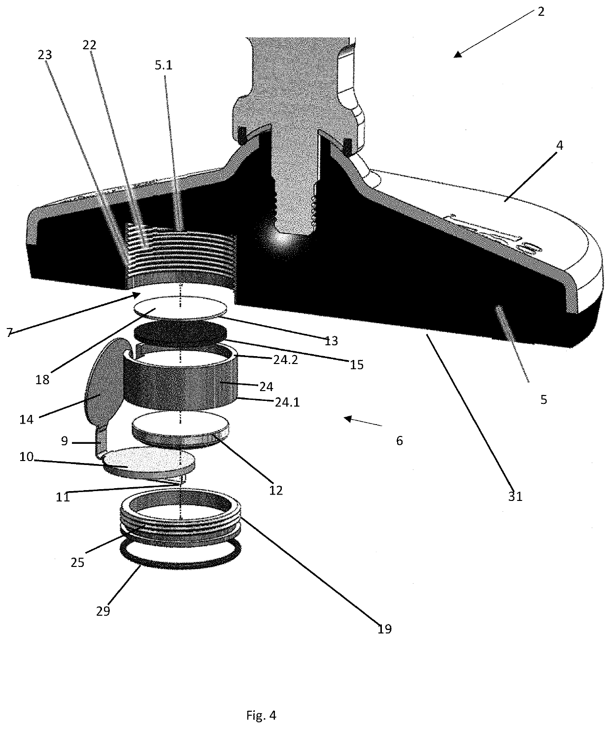
[0112]FIGS. 1-5 show the leveling block / machine foot 1 comprising a top part 3 for sealing in an aggregate such as a machine, as well as an under part 2 for contact with a foundation 31, such as a floor, such that the under part 2 includes a cap 4, and a mainly annular sealing material 5 which is housed in the cap 4 and partially enclosed in it. The top part 3, also referred to as the “spacer” since it creates distance between the machine and under part 3, a distance that can be adjustable, as explained below. Sealing material 5 is made from a rubber-elastic material and also referred to as “the rubber-elastic body”. The rubber-elastic body 5 or the sealing material 5 is usually vulcanised directly togethe...


PUM


Abstract

The invention relates to a method for the establishment of a signal which is indicative of the pressure-condition of a machine foot, as a fixed surface of a rubber-elastic body, where a load of the machine foot is transferred from a cap to a substrate through the rubber-elastic body, which is pressurised by the increasing load, such that the distance between a free upper surface part of the rubber-elastic body and an immobile part is determined by an electro-mechanical transducer establishing an electrical signal corresponding to the distance which is used as the measurement for the rubber-elastic body's pressure-condition and thus the machine foot's load.

Description

CROSS-REFERENCE TO RELATED APPLICATIONS[0001]This application is a continuation-in-part of U.S. application Ser. No. 15 / 750,170 filed Feb. 2, 2018, which was the U.S. national stage of International Appl. No. PCT / DK2016 / 050254 filed Jul. 20, 2016, and which claimed priority to Danish Appl. No. PA 2015 70500 filed Aug. 3, 2015, which applications are incorporated herein by reference in their entireties.TECHNICAL FIELD[0002]The method involves the load of a machine foot being transferred from a rigid cap to a substrate through the rubber-elastic body, the pressure of which is set with the increasing pressure load. A free surface part of the rubber-elastic body will thus move in relation to an immovable part, such as the rigid cap. The new and special aspect of the invention consists of the movement being determined by an electro-mechanical transducer establishing an electrical signal corresponding to the distance. This signal is used as the target for the rubber-elastic body pressure-...

Claims


Application Information

Patent Timeline
IPC IPC(8): G01L1/16G01L1/20F16M7/00A47B91/02
CPCG01L1/20F16M2200/08F16M7/00A47B91/024G01L1/16A47B91/022G01L1/142G01L5/0076
Inventor OLSEN, TOMAS HECHT
Owner NGI AS
Learn More