Mixing device for extruders

Active Publication Date: 2006-05-02
M R S ITAL
View PDF17 Cites 4 Cited by
  • Summary
  • Abstract
  • Description
  • Claims
  • Application Information

AI Technical Summary

Benefits of technology

[0013]Accordingly, it is an aim of the present invention to propose a mixing device for extruders ensuring a high homogeneity of the material coming out of the extrusion cylinder.
[0014]In more detail, it is an aim of the present invention to propose a mixing device for extruders enabling an optimal plasticization of the material to be obtained without increasing the cylinder temperature too much.
[0015]It is a further aim of the invention to provide a mixing device for extruders optimizing the resin mixing by reducing the memory lattices of the polymers composing the resins.

Problems solved by technology

One of the main problems typical of the extrusion screws of the traditional type is an insufficient homogeneity of the material that adversely affects the final product obtained by drawing or molding.
Finally, when resins of different color and nature are processed, an incomplete mixing of same leads to production of articles of manufacture in which regions of different color are recognizable due to the prevalence of a resin with respect to the other.

Method used


Image

  • Mixing device for extruders
  • Mixing device for extruders
  • Mixing device for extruders

Examples


Embodiment Construction

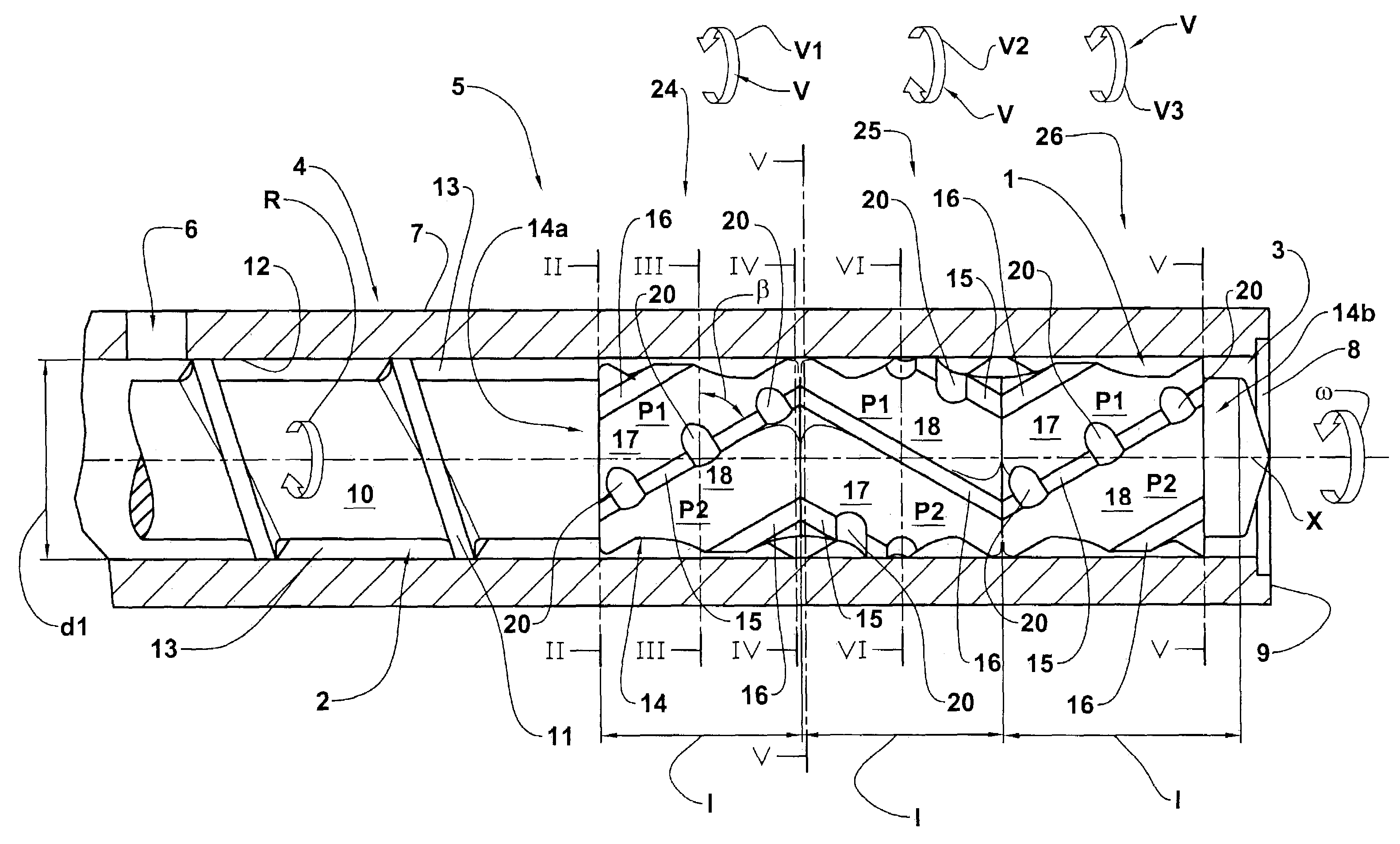
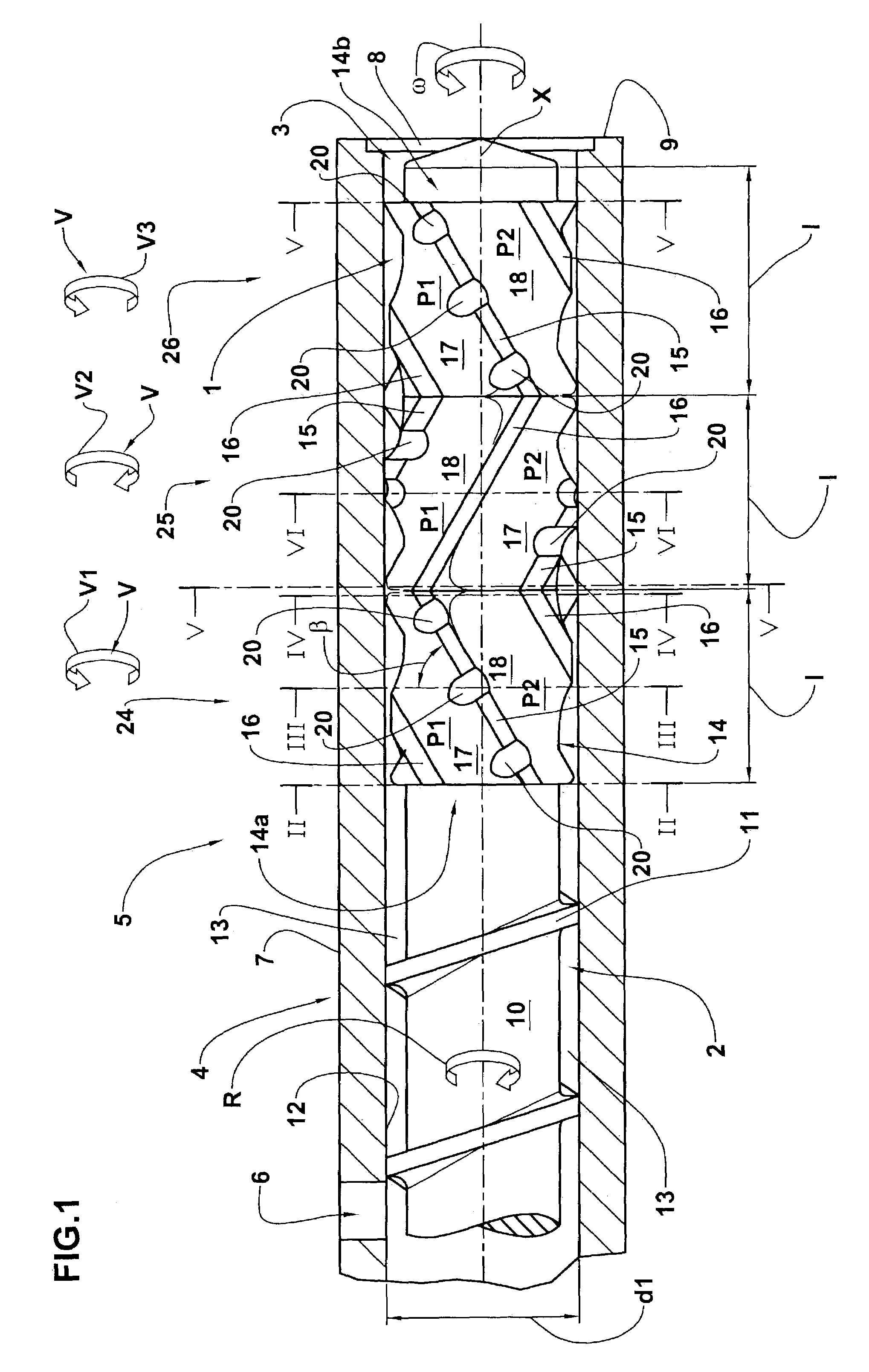
[0024]Referring in particular to the above drawings, a mixing device for extruders in accordance with the present invention has been generally identified by reference numeral 1.

[0025]Device 1 is coaxially mounted on an extrusion screw 2, preferably at an outlet end 3 thereof for material exit. Screw 2 is installed in a tubular body of known type only partly illustrated in FIG. 1 and is set in rotation by appropriate drive means, not shown. The screw 2, tubular body 4 and drive means all together define an extrusion apparatus or extruder 5.

[0026]Extruder 5 has an inlet opening 6, formed in a side wall 7 of the tubular body 4 and diagrammatically shown in FIG. 1, and an outlet opening 8 formed in a base 9 of the tubular body 4, at the outlet end 3 of screw 2. The tubular body 4 is further provided with appropriate heating elements, not shown, preferably defined by one or more resistances buried in the thickness of the body 4 itself.

[0027]Screw 2 extends between the inlet 6 and outlet ...


PUM

PropertyMeasurementUnit
Angleaaaaaaaaaa
Angleaaaaaaaaaa
Angleaaaaaaaaaa

Abstract

A mixing device comprises a cylindrical body (14) to be terminally engaged with an extrusion screw (2) and carrying at least one primary mixing thread (15) and at least one secondary mixing thread (16) having a crest diameter (d3) smaller than the crest diameter (d1) of the primary mixing thread (15). The primary mixing thread (15) has a helical extension in the same direction as that of the secondary mixing thread (16), to delimit at least one primary flow channel (17) and at least one secondary flow channel (18) that are substantially parallel. The primary mixing thread (15) further has, on its crest (19), communication grooves (20) between the primary (17) and secondary (18) flow channels.

Description

BACKGROUND OF THE INVENTION[0001]The present invention relates to a mixing device for extruders comprising a substantially cylindrical body to be terminally engaged with an extrusion screw having a shank and a transportation thread helically wound on the shank; and at least one primary mixing thread helically wound at least partly around the substantially cylindrical body in a predetermined winding direction and having a predetermined crest diameter.[0002]1. Field of the Invention[0003]It is known that in the plastic-material field as regards working and production of articles of manufacture, rotating-screw extruders are used into which the plastic material in granular form is introduced to obtain a compound at the exit which is adapted for subsequent drawing or injection operations in appropriate die-casting molds or others. In many cases the extruder is part of a so-called “plasticizing unit” directly connected to a mold, a rolling set or other type of device for shaping or formin...

Claims


Application Information

Patent Timeline
IPC IPC(8): B29B7/42B29C48/03B29C48/65B29C48/67
CPCB29C47/625B29C47/62B29C47/60B29C47/0009B29C48/03B29C48/65
Inventor SASSI, DARIO IVANSANT'ELIA, FRANCESCO
Owner M R S ITAL
Why Eureka
Try Eureka