Radio base station, wireless terminal, radio communication system, transmission power controlling method, control circuit and program storage medium
a wireless terminal and radio communication system technology, applied in power management, site diversity, diversity/multi-antenna systems, etc., can solve the problem that the control of the individual sinr values of the trps included in the radio base station cannot be performed, the different transmission power control commands cannot be used for each of the trps, and the interference power of other wireless terminals may also be different among the trps
- Summary
- Abstract
- Description
- Claims
- Application Information
AI Technical Summary
Benefits of technology
Problems solved by technology
Method used
Image

Examples
first embodiment
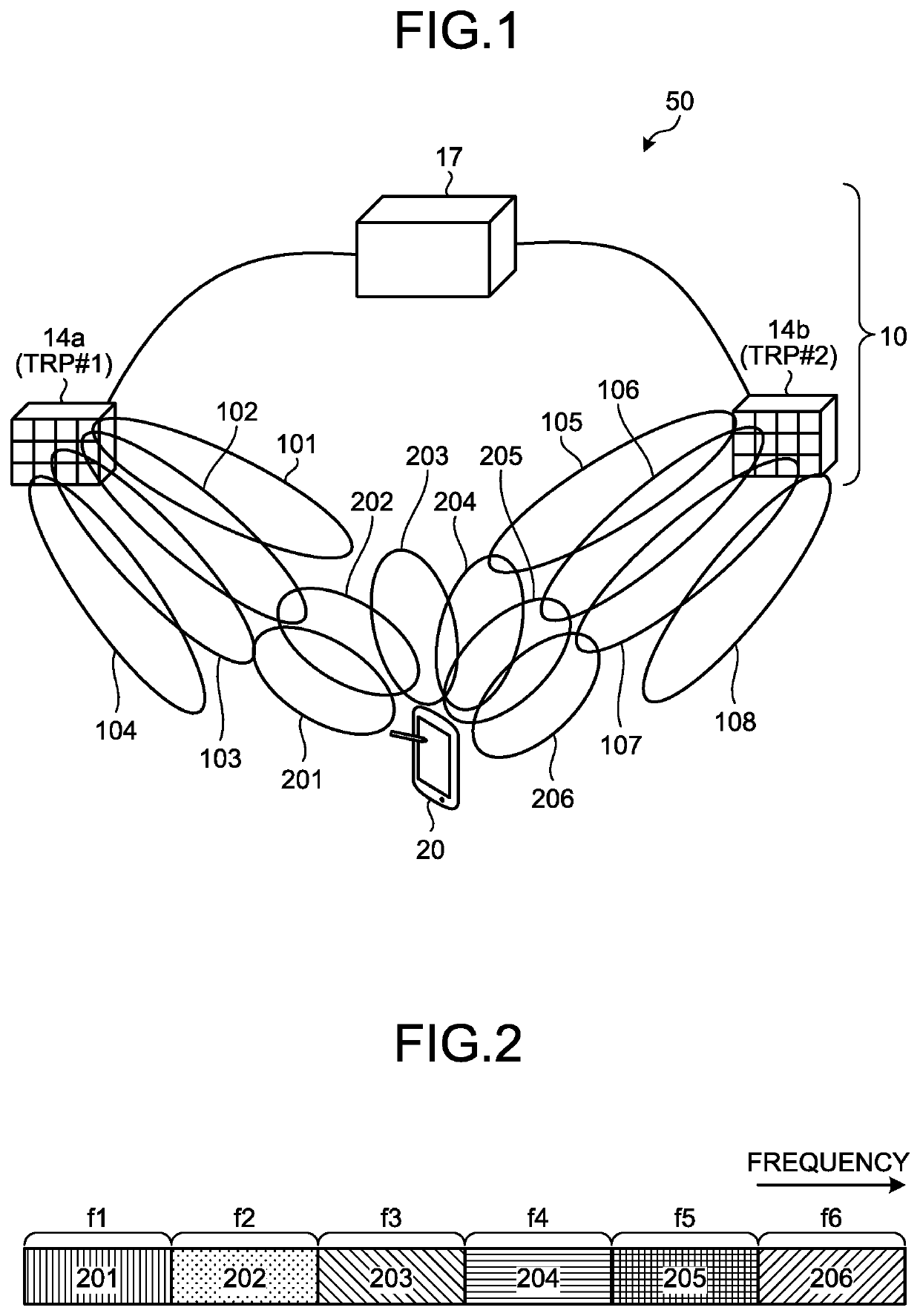
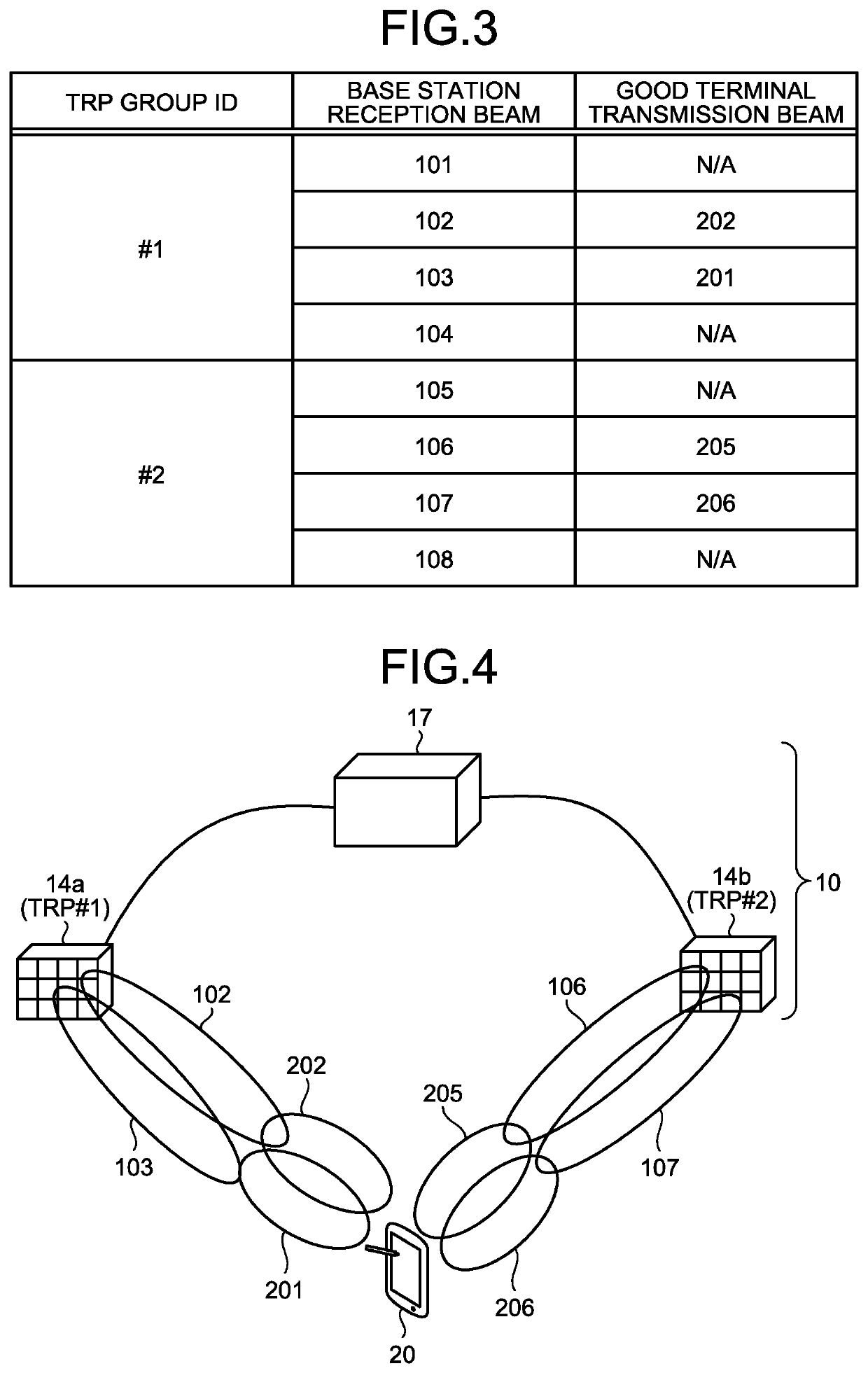
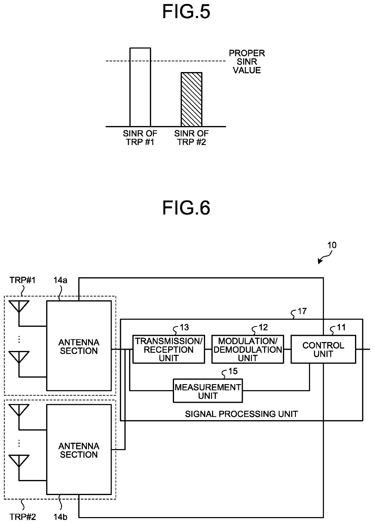
[0034]In the present embodiment, assume a radio communication system, in which the wireless terminal generates a transmission beam and the radio base station generates a reception beam to perform radio communication therebetween when a radio base station receives a signal transmitted from a wireless terminal. While a case where the radio base station includes two TRPs will be described in the present embodiment, the number of TRPs of the radio base station is not limited to two. Hereinafter, one or more beams associated with one TRP will be referred to as a TRP group. Specifically, a reception beam generated by one TRP in the radio base station belongs to one TRP group, and one or more transmission beams generated to be directed toward one TRP by the wireless terminal also belongs to one TRP group. The radio base station applies a transmission power control command in units of TRP groups, that is, controls transmission power of transmission beams of the wireless terminal in units of...
second embodiment
[0069]In the first embodiment, the radio base station 10 groups the terminal transmission beams of the wireless terminal 20. In a second embodiment, a case where the wireless terminal groups the terminal transmission beams will be described. In the second embodiment, assume that so-called beam correspondence, which means that base station transmission beams and base station reception beams form the same gain patterns as each other, is satisfied at each of the TRPs of the radio base station. The base station transmission beams are transmission beams generated at the respective TRPs of the radio base station of the second embodiment for transmission of signals to the wireless terminal. In addition, assume that the so-called beam correspondence, which means that terminal transmission beams and terminal reception beams form the same gain patterns as each other, is satisfied in the wireless terminal as well. The terminal reception beams are reception beams generated in the wireless termi...
third embodiment
[0083]While the radio base station 10 transmits transmission power control commands correspondingly associated with TRP groups at the same time to the wireless terminal 20 in the first embodiment, the transmission power control commands need not necessarily be transmitted at the same time. In a third embodiment, a case where the radio base station 10 transmits transmission power control commands one by one, each command being associated with one TRP group at timings different from each other will be explained. Although this case is also applicable to the radio base station l0a of the second embodiment, an example of application to the radio base station 10 of the first embodiment will be explained because the operations in the second embodiment are similar to those in the first embodiment.
[0084]In the third embodiment, only one definition of a transmission power control command “TPC command for scheduled PUSCH” is sufficient, and the radio base station 10 alternatively notifies the ...
PUM
 Abstract
Description
Claims
Application Information
 - R&D Engineer
- R&D Manager
- IP Professional
- Industry Leading Data Capabilities
- Powerful AI technology
- Patent DNA Extraction
Browse by: Latest US Patents, China's latest patents, Technical Efficacy Thesaurus, Application Domain, Technology Topic.
© 2024 PatSnap. All rights reserved.Legal|Privacy policy|Modern Slavery Act Transparency Statement|Sitemap