Design adjustment based on user-specified direction of change

a technology of user-specified direction and adjustment, applied in the field of design technology, can solve problems such as time-consuming or technical difficulty in actual implementation of these changes

Inactive Publication Date: 2020-12-10
SALESFORCE COM INC
View PDF0 Cites 7 Cited by
  • Summary
  • Abstract
  • Description
  • Claims
  • Application Information

AI Technical Summary

Benefits of technology

The patent text describes a technology for automatically adjusting low-level parameters in user interface design. This technology allows for efficient and effective customization of user interfaces without requiring significant amounts of time or technical expertise. It uses a combination of design techniques and genetic function modules to customize user interface parameters such as formatting, brush elements, and genetic functions. The technology also includes a user interface customization module and a genetic function module for adjusting user interface parameters. The patent text also describes the use of the technology in a computing system. Overall, the technology simplifies the process of creating and customizing user interfaces.

Problems solved by technology

Users or designers may have ideas for the general direction of desired changes to an interface style, but actually implementing these changes may be technically difficult or time consuming.

Method used


Image

  • Design adjustment based on user-specified direction of change
  • Design adjustment based on user-specified direction of change
  • Design adjustment based on user-specified direction of change

Examples


example method

[0035]FIG. 4 is a flow diagram illustrating a method 400 for customizing a user interface, according to some embodiments. The method shown in FIG. 4 may be used in conjunction with any of the computer circuitry, systems, devices, elements, or components disclosed herein, among others. In various embodiments, some of the method elements shown may be performed concurrently, in a different order than shown, or may be omitted. Additional method elements may also be performed as desired.

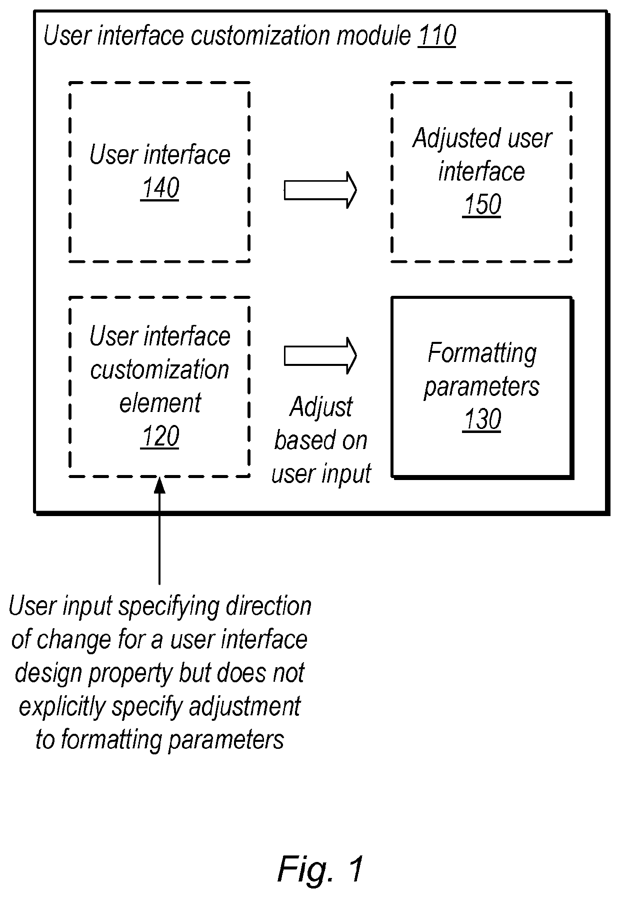
[0036]At 410, in the illustrated embodiment, a computer system displays, in a user interface customization program, a user interface that is formatted according to a plurality of formatting parameters. The interface may be an existing interface or an interface that has already been at least partially modified by the customization program.

[0037]At 420, in the illustrated embodiment, the system displays a user interface customization element in the user interface customization program. The user interface cu...

example device

[0041]In some embodiments, any of various operations discussed herein may be performed by executing program instructions stored on a non-transitory computer readable medium. In these embodiments, the non-transitory computer-readable memory medium may be configured so that it stores program instructions and / or data, where the program instructions, if executed by a computer system, cause the computer system to perform a method, e.g., any of a method embodiments described herein, or, any combination of the method embodiments described herein, or, any subset of any of the method embodiments described herein, or, any combination of such subsets.

[0042]Referring now to FIG. 5, a block diagram illustrating an exemplary embodiment of a device 500 is shown. The illustrated processing elements may be used to implement all or a portion of the module of FIG. 1, in some embodiments. In some embodiments, elements of device 500 may be included within a system on a chip. In the illustrated embodimen...


PUM


Abstract

Disclosed techniques relate to customization of user interface designs based on user input that specifies high-level design properties. In some embodiments, a system displays a user interface in a user interface customization program. In some embodiments, based on user input via a customization interface element that specifies a direction or change for a design property, the system performs an adjustment to formatting parameters for the user interface, where the user input does not explicitly specify the adjustment to the formatting parameters. The system may display an adjusted user interface that exhibits the adjusted formatting parameters.

Description

BACKGROUNDTechnical Field[0001]Embodiments described herein relate to design technology and, in particular, to automated adjustment of low level parameters such as user interface parameters.Description of the Related Art[0002]User interfaces are often generated by multiple skilled designers, e.g., to combine quality coding techniques with graphical design to achieve desired functionality while pleasing the eye, achieving branding goals, or promoting desired user behaviors. Users or designers may have ideas for the general direction of desired changes to an interface style, but actually implementing these changes may be technically difficult or time consuming.BRIEF DESCRIPTION OF THE DRAWINGS[0003]FIG. 1 is a block diagram illustrating an example user interface customization module, according to some embodiments.[0004]FIG. 2 is a diagram illustrating an example user interface with a brush element for user interface customization, according to some embodiments.[0005]FIG. 3 is a diagra...

Claims


Application Information

Patent Timeline
IPC IPC(8): G06F3/0484
CPCG06F2203/04804G06F3/0482G06F3/04845G06F3/04847
Inventor SCHOPPE, OWEN WINNELONSDORF, BRIAN J.ROHDE, SÖNKE
Owner SALESFORCE COM INC
Why Eureka
Try Eureka