

Display integratable hybrid transparent antenna
Inactive Publication Date: 2020-12-10
APPLE INC
View PDF0 Cites 2 Cited by
- Summary
- Abstract
- Description
- Claims
- Application Information
AI Technical Summary
Benefits of technology
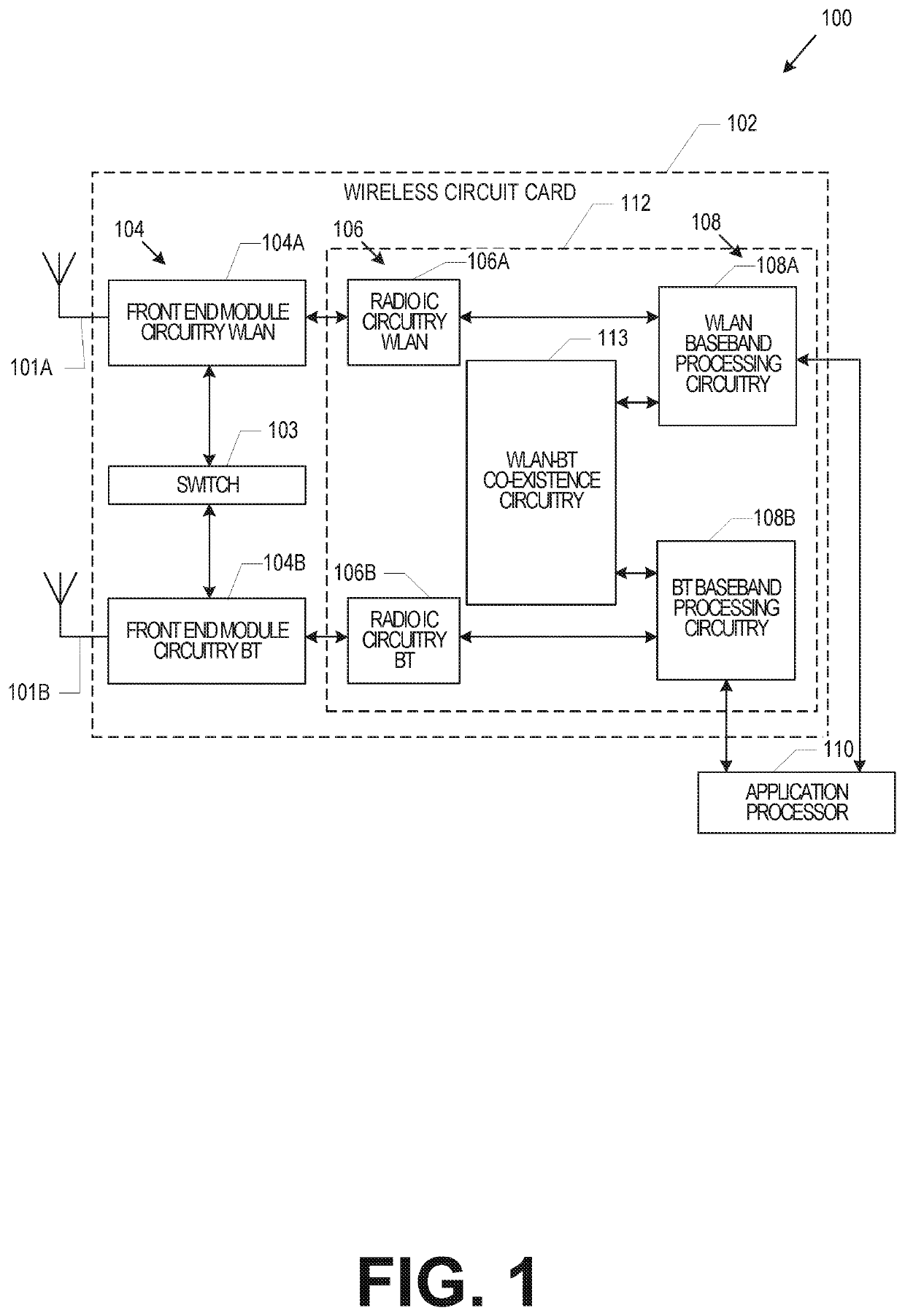
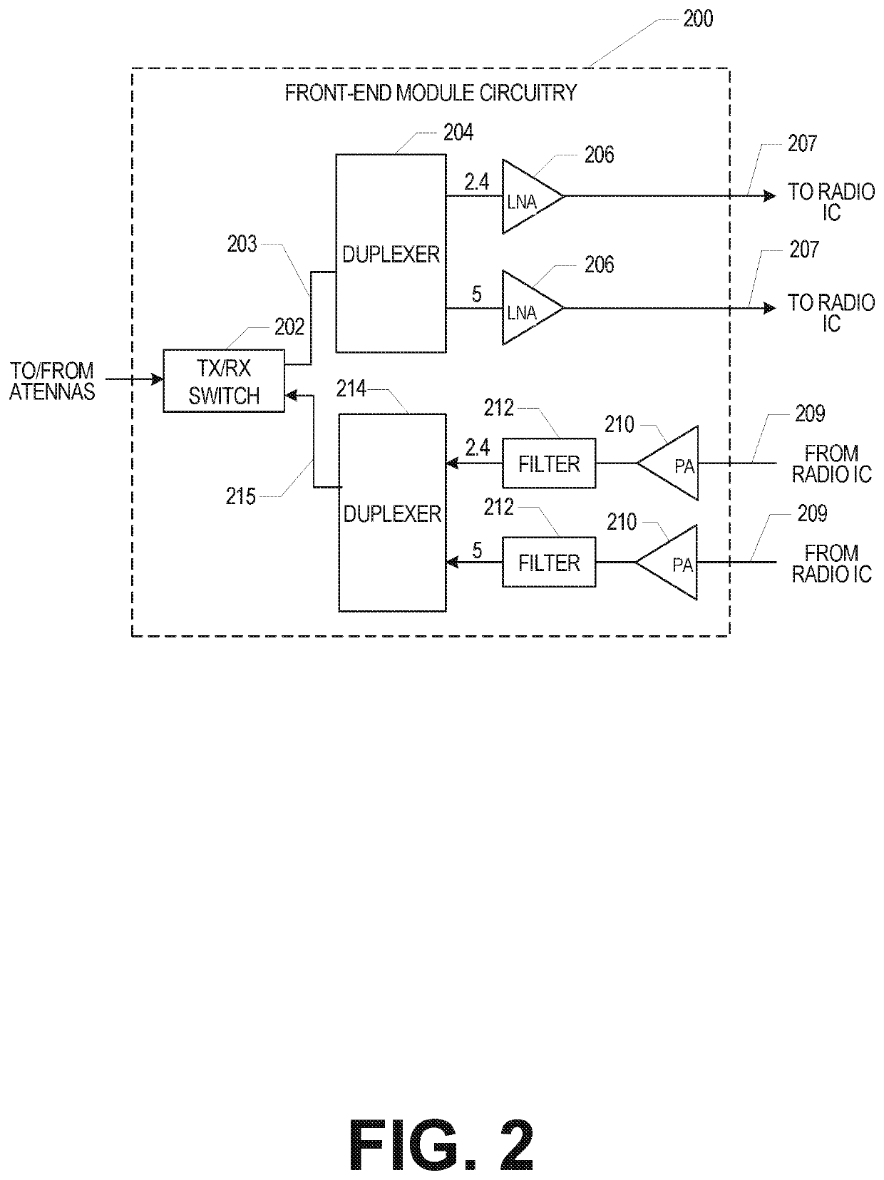
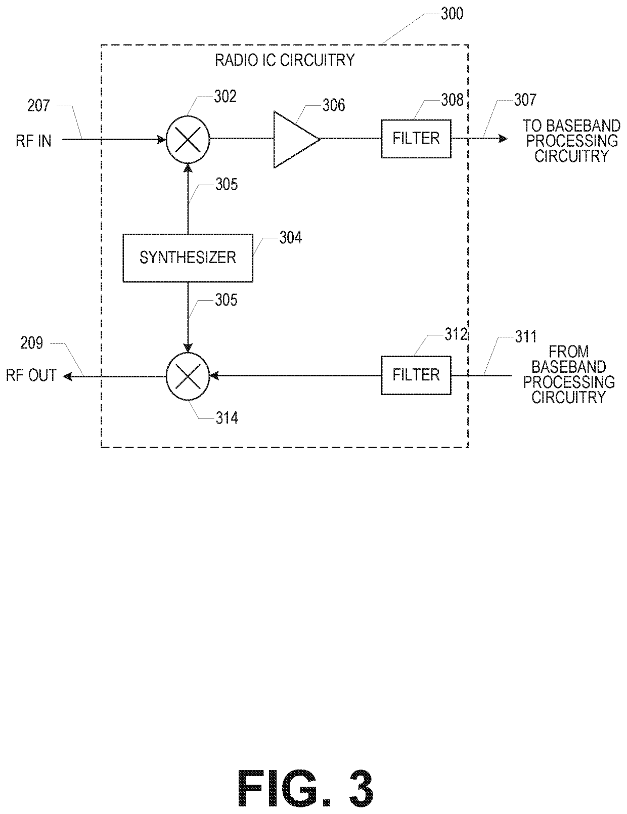
The patent text describes a technology for integrating wireless antennas into display devices, such as smartwatches or other wearable or portable devices. The technology allows for the antennas to be integrated into the display without affecting the overall design of the device. The patent also describes various components of the radio architecture, including the front-end module circuitry, radio IC circuitry, and baseband processing circuitry. The integration of antennas into display devices can improve wireless communication and support more wireless radios in the device. The technology can be used in devices like smartwatches or other wearable or portable devices.
Problems solved by technology
Antenna solutions for such devices can be challenging.
Typically, the antennas in some devices are hidden in a large bezel area surrounding the display, however, the bezel area becomes smaller and smaller and in some instances bezel-less implementations are possible.
Method used
View moreImage
Smart ImageViewing Examples

Examples
example 24
[0111 is a method to implement of any of Examples 1-20.
Login to View More PUM
 Abstract
An apparatus for a wireless device includes a radio front end module (RFEM) configured to generate radio frequency (RF) signals. The apparatus further includes a multi-layer display, including a liquid crystal display (LCD) layer, a touch panel layer, and a cover glass layer. The apparatus further includes an antenna configured to transmit the RF signals. The antenna includes a primary coupling feeding structure, configured to receive the RF signals from the radio front end module via a feed line. The antenna also includes a generating structure configured to radiate the RF signals. The generating structure is alternating current (AC) operably coupled to the primary coupling feeding structure and is within a visible portion of the multi-layer display. The primary coupling feeding structure can include a non-transparent material and is disposed in a non-visible area of the cover glass layer.
Description
PRIORITY CLAIM[0001]This application claims the benefit of priority to U.S. Provisional Patent Application Ser. No. 62 / 590,987, filed Nov. 27, 2017, and entitled “DISPLAY INTEGRATABLE HYBRID TRANSPARENT ANTENNA,” which provisional patent applications is incorporated herein by reference in its entirety.TECHNICAL FIELD[0002]Aspects described herein relate generally to methods and apparatuses for wireless communication. More particularly, aspects relate to antennas and antenna structures. Some aspects of the present disclosure pertain to display integratable antennas and antenna structures. Some aspects of the present disclosure pertain to wireless communication devices (e.g., wearable devices and other computing devices with a predominant display feature, such as mobile devices with touch-enabled display or another type of display). Some aspects of the present disclosure relate to display integratable hybrid transparent antennas, e.g., as used in wearable or other portable devices.BAC...
Claims
Login to View More Application Information
Patent Timeline
 IPC IPC(8): H01Q1/44G06F3/041H01Q9/04H01Q21/28
CPCH01Q9/0407H01Q21/28H01Q1/44H01Q5/40G06F3/041G02F1/13338G06F3/0416G06F3/044G06F3/04164G06F3/0448H01Q1/2266H01Q1/243H01Q1/273H01Q7/00H01Q9/0414
InventorCHAI, MEIHORINE, BRYCE D.SKINNER, HARRY G.YANG, TAE-YOUNG
OwnerAPPLE INC