
Electronic device comprising removable adhesive member

a technology of adhesive member and electronic device, which is applied in the direction of electrical apparatus casing/cabinet/drawer, other domestic articles, etc., can solve the problems of difficult to separate an adhesive member remaining on the surface of the housing or the conductive member, unwanted damage may occur in the stacked member, and the conductive member also has to be replaced, etc., to achieve the effect of improving the adhesive structure, easy separation, and easy separation

Active Publication Date: 2020-12-10
SAMSUNG ELECTRONICS CO LTD
View PDF3 Cites 1 Cited by
  • Summary
  • Abstract
  • Description
  • Claims
  • Application Information

AI Technical Summary

Benefits of technology

The patent text describes an electronic device with a removable adhesive member that can be easily separated to replace electronic components. The adhesive member has decreased adhesive strength when a specific physical property, such as heat or ultrasonic, is applied. This allows for easy separation of the adherend. The invention also provides an electronic device with a removable adhesive member that can be easily separated, and an improved adhesive structure that can be separated after the separation for efficient maintenance of the electronic device.

Problems solved by technology

However, since at least one adhesive member disposed between the display and the housing has the same adhesive strength, an unwanted damage may occur in the stacked member when the display is separated.
For example, when the display is separated, if a conductive member (e.g., a Cu sheet) disposed therebetween is not separated together with the display but remains in the housing, there may be a problem in that the conductive member also has to be newly replaced.
In addition, even if the conductive member is separated together with the display, there may be a problem in that it is difficult to separate an adhesive member remaining on a surface of the housing or the conductive member.

Method used


Image

  • Electronic device comprising removable adhesive member
  • Electronic device comprising removable adhesive member
  • Electronic device comprising removable adhesive member

Examples


Embodiment Construction

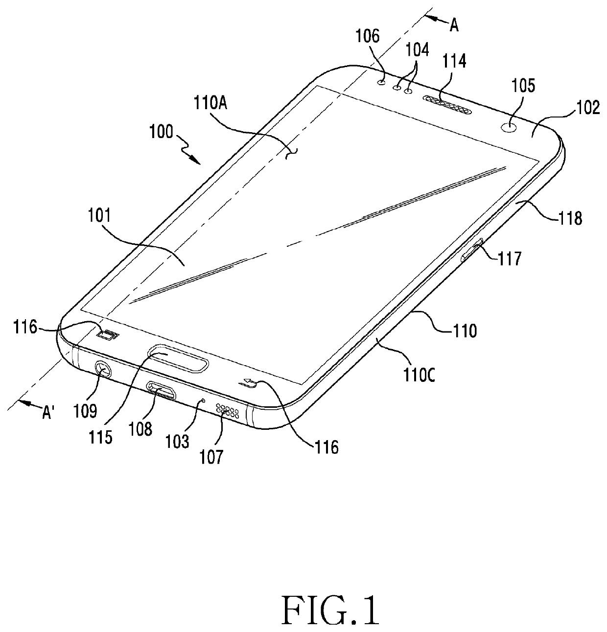
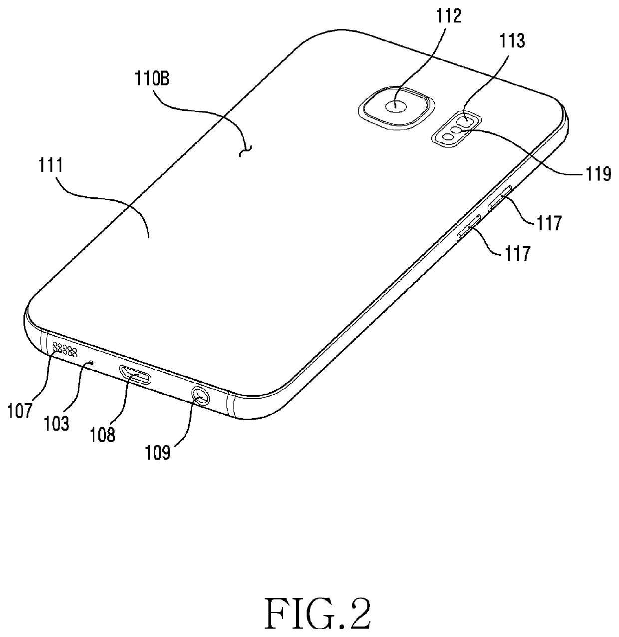
[0032]FIG. 1 is a front perspective view illustrating an example mobile electronic device according to various embodiments. FIG. 2 is a rear perspective view illustrating an example mobile electronic device of FIG. 1.

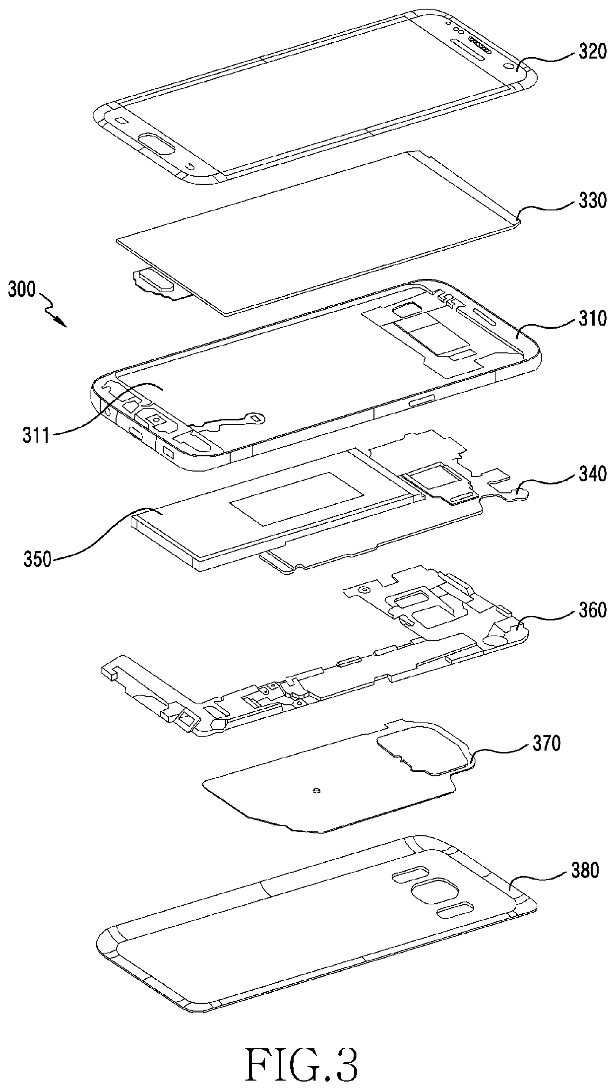
[0033]Referring to FIG. 1 and FIG. 2, an electronic device 100 according to an embodiment may include a housing 110 including a first side (or a front side) 110A, a second side (or a rear side) 110B, and a lateral side (surface) 110C surrounding a space between the first side 100A and the second side 110B. In another embodiment (not shown), the housing may refer to a structure which includes part of the first side 110A, second side 110B, and third side 110C of FIG. 1. According to an embodiment, the first side 110A may be constructed of a front plate 102 (or a front cover) (e.g., a polymer plate or a glass plate having various coating layers) which is at least partially transparent. The second side 110B may be constructed of a rear plate 111 (or a rear cover) which may ...


PUM

PropertyMeasurementUnit
Thicknessaaaaaaaaaa
Lengthaaaaaaaaaa
Adhesion strengthaaaaaaaaaa

Abstract

According to various embodiments, an electronic device may include a housing including a first side, a second side facing away from the first side, and a lateral side surrounding a space between the first side and the second side, a front plate disposed on the first side of the housing, a display disposed between the front plate and the first side such that at least part thereof is exposed through the front plate, at least one functional member disposed between the display and the first side, and an adhesive member disposed between the functional member and the first side to attach the functional member to the housing, wherein adhesive member includes an adhesive portion for attaching the functional member and the first side, and at least one non-adhesive portion extending from the adhesive portion. Various other embodiments are possible.

Description

CROSS-REFERENCE TO RELATED APPLICATIONS[0001]This application is a 371 National Stage of International Application No. PCT / KR2018 / 015044, filed Nov. 30, 2018, which claims priority to Korean Patent Application No. 10-2017-0174239, filed Dec. 18, 2017, the disclosures of which are herein incorporated by reference in their entirety.BACKGROUND1. Field[0002]Various embodiments of the present disclosure relate to an electronic device including a removable adhesive member.2. Description of Related Art[0003]With a significant decrease in a functional gap of each manufacturer, an electronic device has become slimmer to satisfy purchasing needs of consumers, and is under development to improve rigidity of the electronic device and to differentiate functional elements thereof while enhancing a design aspect.[0004]The electronic device may include a plurality of electronic components disposed therein, and may be efficiently disposed in consideration of space utilization. According to an embodi...

Claims


Application Information

Patent Timeline
IPC IPC(8): H05K5/00B32B7/14H04M1/02
CPCB32B7/14H05K5/0017H04M1/0266B32B2457/00H04M1/0249B32B7/12B32B15/18B32B15/20B32B2307/412B32B15/08B32B2457/208B32B2457/20B32B9/005B32B9/04B32B3/30B32B2307/41B32B27/06H04M1/0254C04B37/005H04R7/18H04M1/035
Inventor KIM, JUNGTAEJANG, HYUKJAELEE, HOONHEELEE, JAEHYUNGJANG, HYEYEON
Owner SAMSUNG ELECTRONICS CO LTD
Learn More