Connector

Active Publication Date: 2020-12-17
JAPAN AVIATION ELECTRONICS IND LTD
View PDF0 Cites 0 Cited by
  • Summary
  • Abstract
  • Description
  • Claims
  • Application Information

AI Technical Summary

Benefits of technology

The invention provides a connector that can easily be attached to a composite cable and automated. The technical effect is that it simplifies the process of connecting cables, making it easier and faster for R&D personnel.

Problems solved by technology

Accordingly, the connector of Patent Document 1 is unsuitable for automatization of being attached to the cables.

Method used


Image

  • Connector
  • Connector
  • Connector

Examples


Embodiment Construction

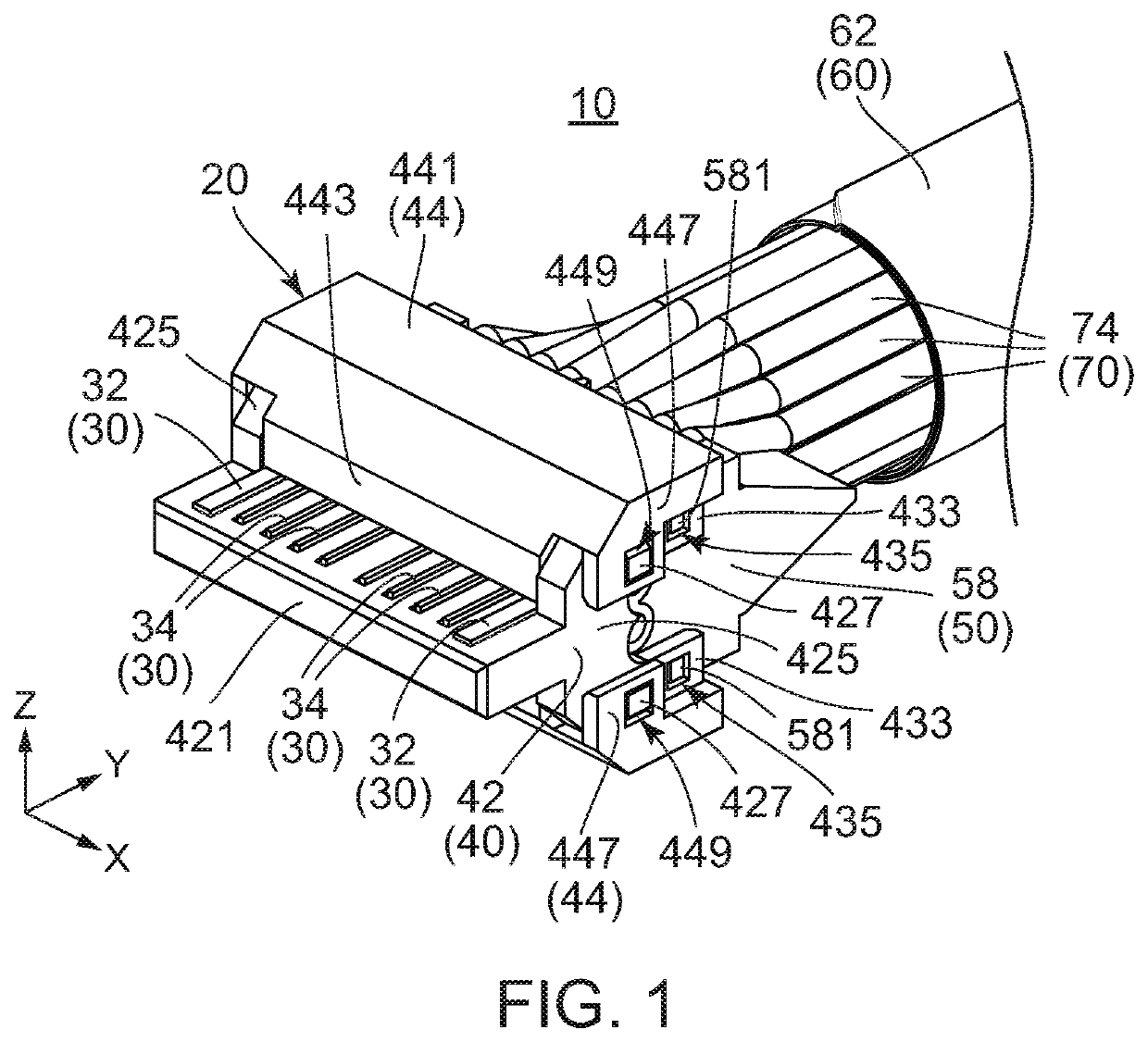
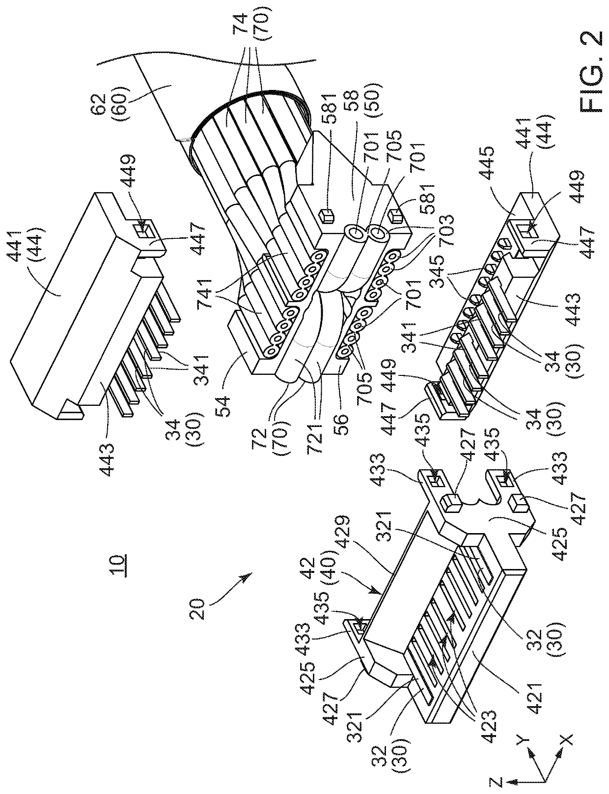
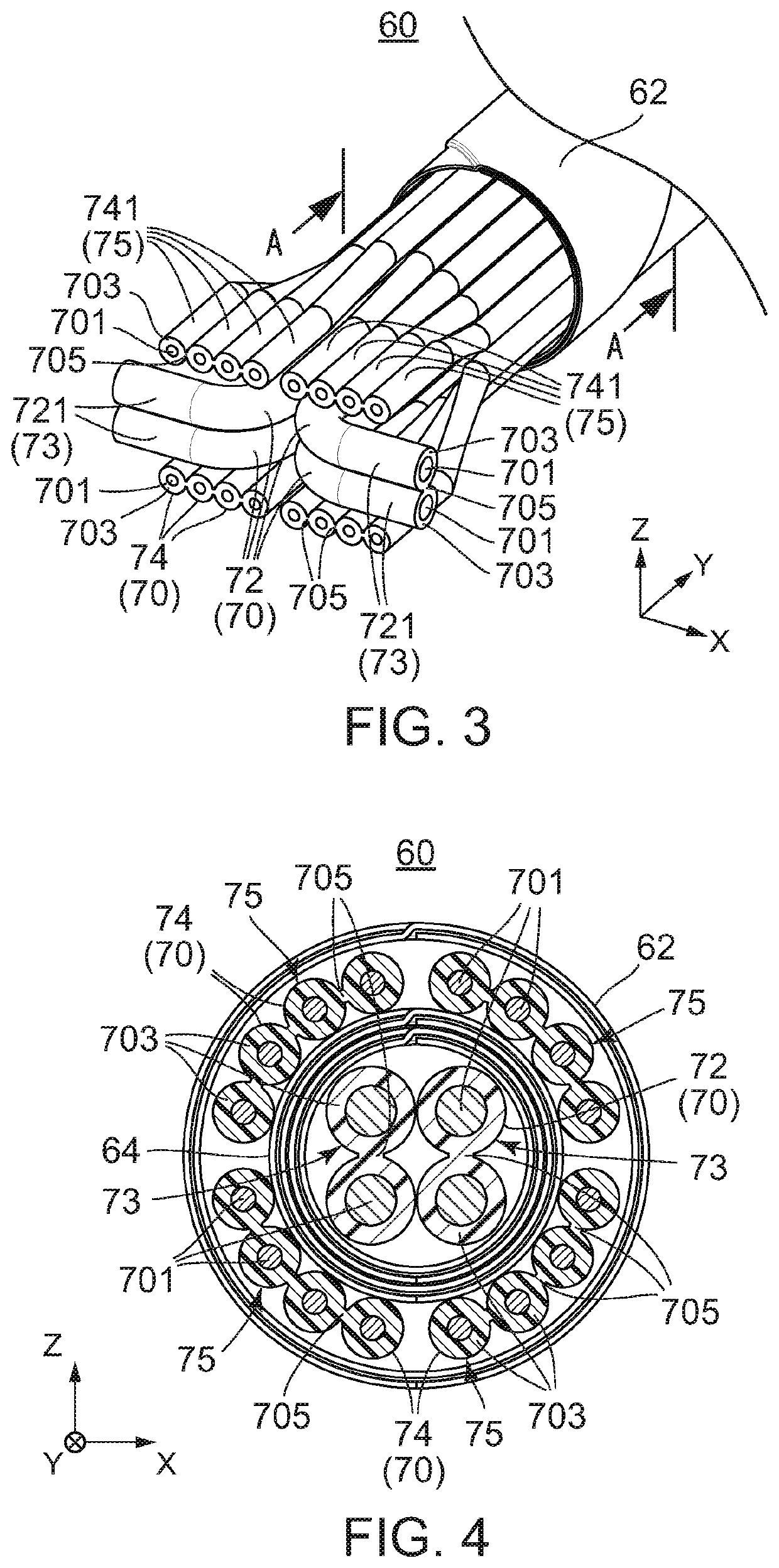
[0026]Referring to FIG. 1, a cable harness 10 according to an embodiment of the present invention is provided with a composite cable 60 and a connector 20 attached to an end of the composite cable 60. The composite cable 60 has a plurality of cables 70 and an outer sheath 62 covering the cables 70. The connector 20 is provided with a plurality of terminals 30 corresponding to the cables 70, respectively.

[0027]Referring to FIG. 2, the connector 20 is provided with a housing 40 holding the terminals 30 and a locator 50 to which the housing 40 is attached. The housing 40 consists of a first housing 42 and a pair of second housings 44. The first housing 42 is formed so as to be attached to the locator 50. The second housings 44 are formed so as to be combined with the first housing 42. The connector 20 attached to the composite cable 60 is formed by attaching the first housing 42 to the locator 50 and then attaching the second housings 44 to the first housing 42.

[0028]As shown in FIGS. ...


PUM


Abstract

A connector is provided with a plurality of terminals and a housing. The terminals include a first terminal corresponding to a first cable and a second terminal corresponding to a second cable. Each of the terminals has a contact portion, a held portion and a connection portion. The contact portion is brought into contact with a mating contact portion when the connector is connected to a mating connector. The held portion is held by the housing. When the connector is attached to a composite cable, the connection portion pierces a covering portion of a cable corresponding thereto and is connected to a conductor of the cable. The connection portion of the first terminal protrudes from the held portion in a front-rear direction. The connection portion of the second terminal protrudes from the held portion in a perpendicular direction.

Description

CROSS REFERENCE TO RELATED APPLICATIONS[0001]This application is based on and claims priority under 35 U.S.C. § 119 to Japanese Patent Application No. JP2019-110501 filed Jun. 13, 2019, the contents of which are incorporated herein in their entirety by reference.BACKGROUND OF THE INVENTION[0002]This invention relates to a connector, particularly, to a connector to be attached to a composite cable.[0003]JP2004-152667A (Patent Document 1) discloses an example of a connector to be attached to a plurality of cables. As shown in FIG. 11, a connector 90 of Patent Document 1 has a housing 92 and a block 94 which is combined with the housing 92. The block 94 is attached to the housing 92 from above of the housing 92. The block 94 is formed with a plurality of receiving holes 940 which receive end portions (not shown) of the cables (not shown), respectively.[0004]As understood from FIGS. 11 and 12, the housing 92 is provided with a plurality of contacts 920 which correspond to the cables (no...

Claims


Application Information

Patent Timeline
IPC IPC(8): H01R12/51H01R12/59
CPCH01R12/592H01R12/515H01R13/02H01R4/2404H01R9/031H01R13/506H01R12/67H01R4/24
Inventor TODA, KENTARO
Owner JAPAN AVIATION ELECTRONICS IND LTD
Why Eureka
Try Eureka