Image display apparatus for vehicle
- Summary
- Abstract
- Description
- Claims
- Application Information
AI Technical Summary
Benefits of technology
Problems solved by technology
Method used
Image
Examples
example 1
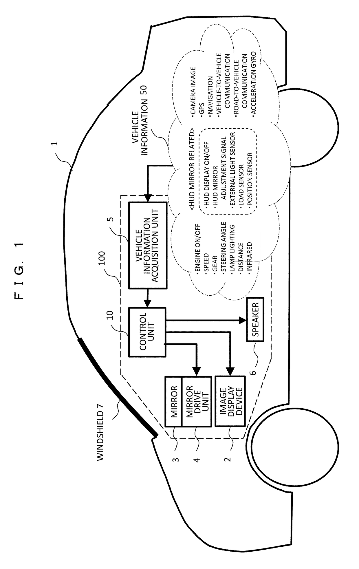
[0074]In an example 1, an example of a mirror adjustment mechanism of a head up display (HUD) according to the present invention will be described. For ease of understanding, the description will be given as compared with a conventional adjustment mechanism.
[0075]FIG. 7 is a diagram illustrating a conventional mirror adjustment method 1. The image light emitted from the image display device 2 is reflected by the mirror 3, reflected at the reflection position 70 of the windshield, and is incident on the driver's eyes 8, and the driver visibly recognizes the image light as the virtual image 9. When the position of the eyes 8 (hereinafter referred to as an eye point) changes to A, B, and C according to a height of the driver, there is a case in which the image light emitted from the image display device 2 cannot be incident on each eye point or there is a case in which a part of the image is lost even if the image light can be incident on the eye point. In order to cope with the above ...
example 2
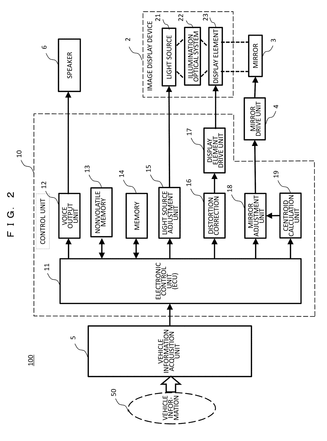
[0103]In the example 1, the configuration in which the optimum position in the mirror adjustment is determined while the driver views the image, that is, a manual adjustment method is employed. On the contrary, in an example 2, a method in which the position of the driver's eyes is calculated, and the position of the mirror is automatically adjusted to an optimum state according to the calculated position of the driver's eyes. In the present example, in order to detect the position of the driver's eyes, the centroid position of the driver is obtained according to the position and load of the driver, and the position of the eyes is calculated according to the centroid position.
[0104]As a result, when the driver changes to another driver, or when the driver's posture changes even with the same driver, the most visible image display can be performed by following the position of the driver's eyes at that time. It should be noted that the adjustment mechanism of the mirror employs the re...
example 3
[0115]In an example 3, in order to move the display area of the image in the right and left direction, a configuration for moving the entire HUD in the dashboard in the right and left direction will be described. The reasons why there is a need to move the display area in the right and left direction will be described below, for example.[0116](1) A case in which the position (eye point) of the driver's eyes moves in the right and left direction.[0117](2) A case in which the posture (centroid position) of the driver moves in the right and left direction.[0118](3) A case in which a vehicle traveling direction changes according to driving operation (steering wheel operation or direction indicator).[0119](4) A case in which the driver's visual line direction changes according to road guidance (right / left turn sign and intersection distance).[0120](5) A case in which the driver's visual line direction changes due to an obstacle (an interruption car or a rush-out pedestrian).
[0121]The cha...
PUM
 Abstract
Description
Claims
Application Information
 - R&D
- Intellectual Property
- Life Sciences
- Materials
- Tech Scout
- Unparalleled Data Quality
- Higher Quality Content
- 60% Fewer Hallucinations
Browse by: Latest US Patents, China's latest patents, Technical Efficacy Thesaurus, Application Domain, Technology Topic, Popular Technical Reports.
© 2025 PatSnap. All rights reserved.Legal|Privacy policy|Modern Slavery Act Transparency Statement|Sitemap|About US| Contact US: help@patsnap.com


