Micro-forging by a generative manufacturing process

a generative manufacturing and micro-forging technology, applied in the direction of additive manufacturing processes, manufacturing tools, non-electric welding apparatuses, etc., can solve the problems of complex and costly post-processing of surfaces by grinding and polishing, and the surface of additively or generatively manufactured components is often not accessible or no longer accessible or difficult to access post-processing tools, etc., to achieve simple operation, simple structure, and simple to conduct

Active Publication Date: 2017-09-07
MTU AERO ENGINES GMBH
View PDF9 Cites 17 Cited by
  • Summary
  • Abstract
  • Description
  • Claims
  • Application Information

AI Technical Summary

Benefits of technology

[0009]It is thus the object of the present invention to provide a method and a device for the additive manufacture of components by layer-by-layer joining of powder particles to one another and / or to an already produced pre-product or substrate, via selective interaction of powder particles with a high-energy beam, in which the above-described problems are avoided or at least reduced. Nevertheless, the method shall be simple to conduct and the device shall be simply constructed and easy to operate, so that the corresponding additive manufacture can be employed in industrial processes.

Problems solved by technology

Of course, in addition, there results the problem that the surfaces of the additively or generatively manufactured component are frequently not accessible or no longer accessible or difficultly accessible to the post-processing tools, in particular when they involve inner-lying surfaces of cavities.
Additionally, a post-processing of the surfaces by grinding and polishing is often complex and costly, in particular when there needs to be a large amount of material removed in order to eliminate defect sites such as pores or microcracks in the surface or in regions near the surface.

Method used


Image

  • Micro-forging by a generative manufacturing process
  • Micro-forging by a generative manufacturing process
  • Micro-forging by a generative manufacturing process

Examples


embodiment

OF EMBODIMENT

[0028]Further advantages, characteristics and features of the present invention will be made clear in the following detailed description of examples of embodiment, the invention not being limited to these embodiment examples.

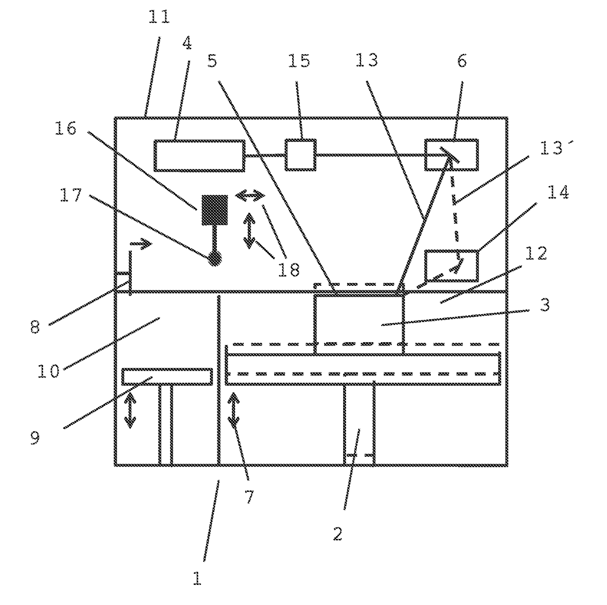
[0029]In a purely schematic representation, FIG. 1 shows a device 1, as can find use, for example, for selective laser melting in the additive manufacture of a component. The device 1 comprises, in a housing 11, a lift table 2 on the platform of which is disposed a semi-finished product or pre-product 3, onto which material is deposited layer by layer in order to produce a three-dimensional component. For this purpose, powder that is found in a powder supply container 10 above a lift table 9, is moved by means of a slider 8, layer by layer, over the pre-product 3 and subsequently joined to the already present pre-product 3 by melting via the laser beam 13 of a laser 4. After completely applying a powder layer 5, the lift table 2 is lowered correspon...


PUM

PropertyMeasurementUnit
weight fractionaaaaaaaaaa
chemical compositionaaaaaaaaaa

Abstract

The present invention relates to a device as well as a method for the additive manufacture of components by deposition of material layers by layer-by-layer joining of powder particles to one another and/or to an already produced pre-product or substrate, via selective interaction of the powder particles with a high-energy beam, wherein, for smoothing a surface of the component being produced running crosswise to the deposited material layers in between the deposition of two layers of the component, the complete edge region of the last layer that is applied and that runs along a surface of the component being produced is compacted in a direction of action that has a directional component parallel to the build-up direction of the layers, and/or at least one edge region (19) of a surface of the component (3′) is also compacted.

Description

BACKGROUND OF THE INVENTION[0001]Field of the Invention[0002]The present invention relates to a method and a device for the generative or additive manufacture of components by layer-by-layer joining of powder particles to one another and / or to an already produced semi-finished product or pre-product or substrate, via selective interaction of the powder particles with a high-energy beam, in particular a method and a device for selective laser-beam or electron-beam melting.[0003]Prior Art[0004]Additive manufacturing methods for the manufacture of a component, such as, for example, selective laser melting, selective electron-beam melting, or laser deposition welding, in which the component is built up layer-by-layer with the use of powder material, are employed in industry for so-called rapid tooling, rapid prototyping, or also for the production of mass-produced products within the scope of rapid manufacturing. In particular, such methods can also be used for the manufacture of turbin...

Claims


Application Information

Patent Timeline
Patent Type & Authority Applications(United States)
IPC IPC(8): B23K26/00B33Y30/00B23K26/342C21D10/00B23K15/00B33Y10/00B33Y40/00
CPCB23K26/0069B33Y10/00B33Y30/00B23K26/342C21D10/005B23K15/0086B33Y40/00B22F2998/10B29C64/153B29C64/188B23K15/0093B23K20/10B23K26/352B23K26/3576Y02P10/25B22F12/41B22F10/38B22F10/28B22F10/50B22F2202/01B23K26/356
Inventor BAMBERG, JOACHIMHESSERT, ROLANDSCHLICK, GEORG
Owner MTU AERO ENGINES GMBH
Why Eureka
Try Eureka