Arrangement of nozzle units for a wiper arm, wiper arm and use of a nozzle unit

Active Publication Date: 2020-12-24
A RAYMOND & CO
View PDF0 Cites 2 Cited by
  • Summary
  • Abstract
  • Description
  • Claims
  • Application Information

AI Technical Summary

Benefits of technology

[0007]Generally, the nozzle unit is adapted to prevent rotation about the longitudinal axis of the wiper arm by a simple form-fitting connection thereto. The provision of a flat contact surface facilitates assembly and ensures that the nozzle orientation does not change inadvertently after assembly. The accuracy with which the liquid is applied to the windshield is thus continuously maintained.
[0008]According to the invention, the nozzle unit comprise or is formed as a rigid body. As a result, the nozzle can be incorporated into the nozzle unit with a higher manufacturing accuracy than is the case with a hose of the aforementioned type. In addition, the nozzle unit does not deform and cause a change of the nozzle's orientation. Typically, the rigid body

Problems solved by technology

A disadvantage of this, however, is that the holes can only be produced such that the holes are subject to a wide tolerance range because of the elastic property of the tube.
Furthermore, because of the elastic behavior of the hose, the hose can twist during installation or during operation, so that the nozzles no longer have the desired orientation.
Overall, these disadvantages lead to the liquid not being applied to the car windshield with the

Method used


Image

  • Arrangement of nozzle units for a wiper arm, wiper arm and use of a nozzle unit
  • Arrangement of nozzle units for a wiper arm, wiper arm and use of a nozzle unit
  • Arrangement of nozzle units for a wiper arm, wiper arm and use of a nozzle unit

Examples


Embodiment Construction

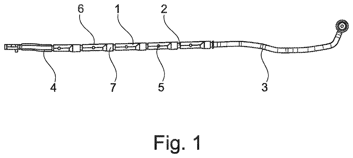
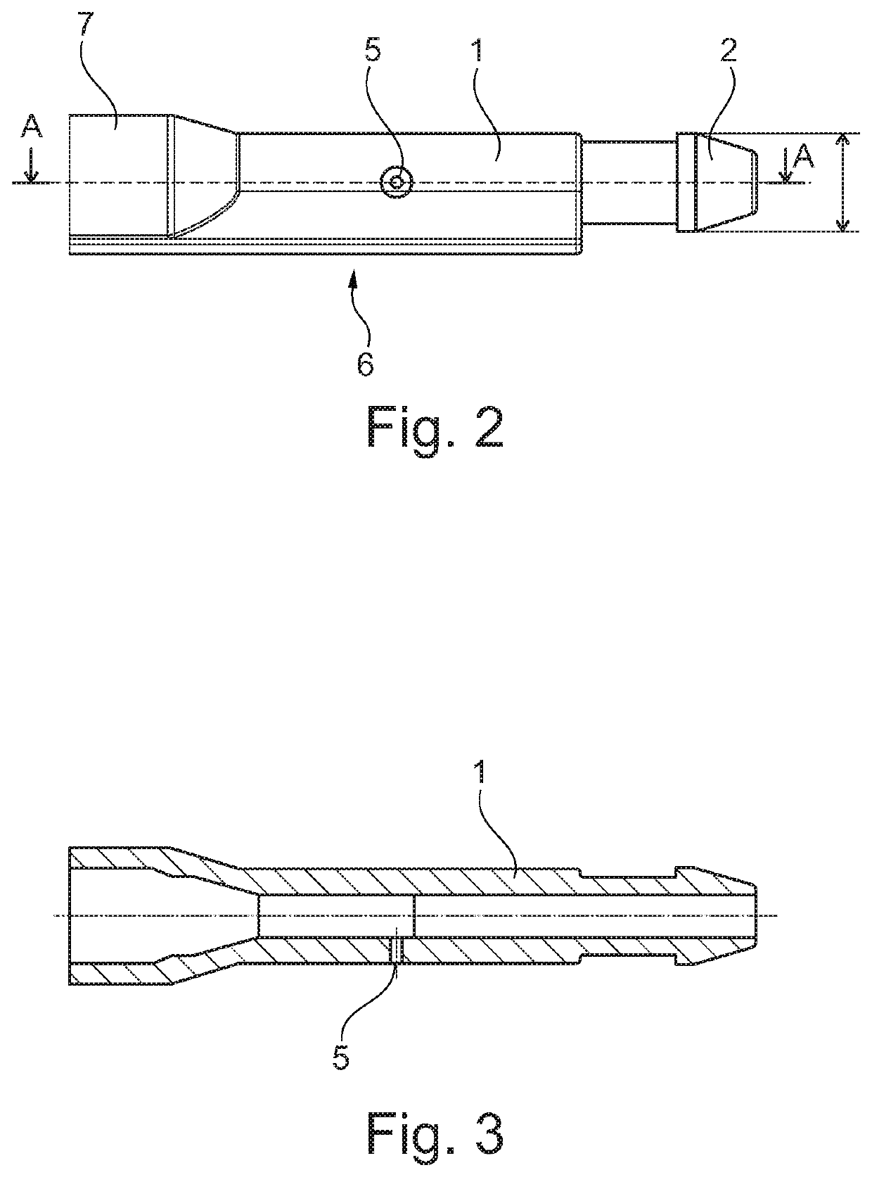
[0058]FIGS. 1 to 3 show an exemplary embodiment of the arrangement. The arrangement comprises five nozzle units 1 connected to each other in series. In this exemplary embodiment, the nozzle units 1 are connected directly to one another. To this end, each nozzle unit 1 comprises a rigid insert 2 and an elastic hollow counterpart 7. The insert 2 of a nozzle unit 1 is inserted into the elastic hollow counterpart 7 of a following nozzle unit 1 in the series. The arrangement is part of a line system of a windshield wiper system. For this purpose, the arrangement is connected on one side to a hose 3 for supplying a liquid, in particular a windshield cleaner, and on the other side to a hose segment 4 for conveying the liquid, for example to a nozzle fastened elsewhere.

[0059]In the present example, each nozzle unit 1 comprises a nozzle 5 for applying the liquid to an auto windshield. All nozzles 5 are oriented identically. Furthermore, each nozzle unit 1 has a flat contact surface 6. The co...


PUM


Abstract

Disclosed is an arrangement of nozzle units for a wiper arm, wherein at least one nozzle unit comprises a rigid body, has a channel through which liquid can flow into the nozzle unit and/or out of the nozzle unit, and comprises a nozzle, which is connected to the channel. The nozzle units are in communication with each other in series such that a liquid can flow from a nozzle unit into a following nozzle unit in the series, wherein at least one nozzle unit has a contact surface which is formed such that the nozzle unit cannot rotate about the longitudinal axis thereof if the contact surface contacts a surface of a wiper arm. A wiper arm comprising the arrangement is also disclosed.

Description

CROSS-REFERENCE TO RELATED APPLICATIONS[0001]This application is the National Stage of International Application No. PCT / EP2018 / 085529, filed on 18 Dec. 2018, which claims priority to and all advantages of German Patent Application No. 10 2017 012 038.2, filed on 22 Dec. 2017, the contents of which are hereby incorporated by reference.FIELD OF THE INVENTION[0002]The present invention generally relates to a nozzle unit and an arrangement of nozzle units for a wiper arm. The invention further relates to a wiper arm and to a use of a nozzle unit for fastening to a surface of a wiper arm.BACKGROUND OF THE INVENTION[0003]A wiper arm is generally known in which a perforated hose is arranged, wherein the holes in the hose serve as nozzles in order to apply a liquid flowing through the hose to a car windshield. A disadvantage of this, however, is that the holes can only be produced such that the holes are subject to a wide tolerance range because of the elastic property of the tube. In addi...

Claims


Application Information

Patent Timeline
IPC IPC(8): B60S1/52B60S1/34
CPCB60S1/3415B60S1/522
Inventor ZIMMER, JOCHENFEGER, AXEL
Owner A RAYMOND & CO
Why Eureka
Try Eureka