
Potentiometric sensor

a technology of potentiometer and sensor, applied in the field of potentiometer, can solve the problems of time-consuming, inconvenient, and inability to meet the needs of measurement,

Active Publication Date: 2020-12-24
THE UNITED STATES AS REPRESENTED BY THE DEPARTMENT OF ENERGY
View PDF0 Cites 0 Cited by
  • Summary
  • Abstract
  • Description
  • Claims
  • Application Information

AI Technical Summary

Benefits of technology

The patent is about a special sensor that can measure the concentration of a certain substance in a liquid. It works by using two different voltages, one from a cathode and one from an anode. The cathode produces a detailed summary of the voltage levels, while the anode produces a single voltage. This information is combined to create a mathematical equation that can be used to calculate the concentration of the target substance in the liquid. This invention helps to create a more accurate and reliable way to measure the concentration of various substances in liquids.

Problems solved by technology

But, currently the concentration of actinides in the fuel salt is usually conducted by chemical analysis, which is time-consuming, inconvenient and not real-time.

Method used


Image

  • Potentiometric sensor
  • Potentiometric sensor
  • Potentiometric sensor

Examples


Embodiment Construction

[0009]The following detailed description provides illustrations for embodiments of the present invention. Each example is provided by way of explanation of the present invention, not limitation of the present invention. Those skilled in the art will recognize that other embodiments for carrying out or practicing the present invention are also possible. Therefore, it is intended that the present invention covers such modifications and variations as come within the scope of the appended claims and their equivalents.

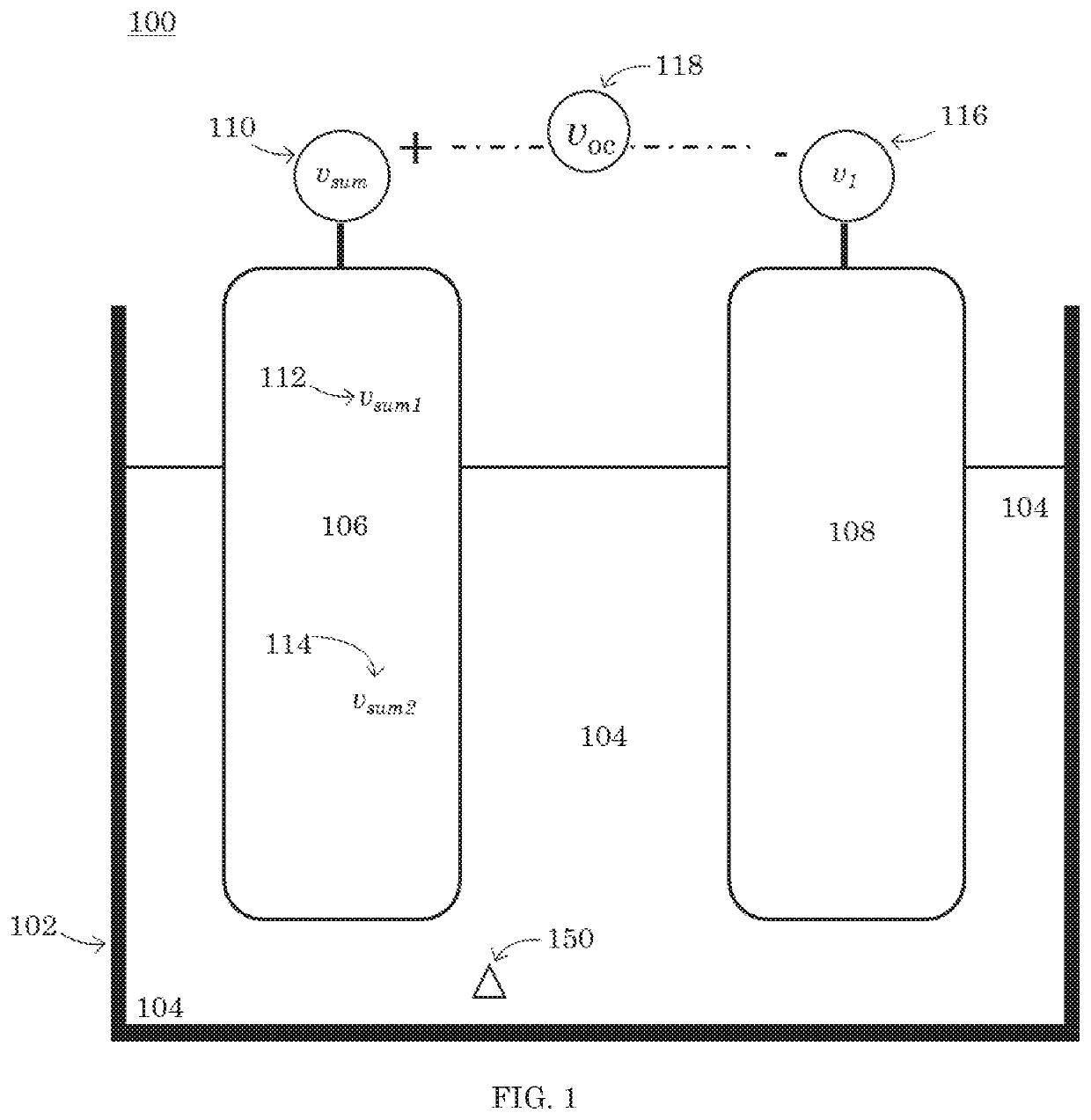
[0010]Referring to FIG. 1, a sectional view of an embodiment of a potentiometric sensor 100 is shown. Within a vessel 102, there is a cathode 106 in communication with an anode 108 through a first electrolyte 104.

[0011]The vessel 102 can be any container capable of operably holding the potentiometric sensor 100. The vessel 102 is made from any material insoluble to and electrically insulated from the contents of the potentiometric sensor 100. For example, the vessel 102 can...


PUM


Abstract

According to one aspect of the invention, a potentiometric sensor having a cathode and an anode. The cathode is configured to provide a summary voltage representative of at least two voltage points. The anode is configured to provide a first voltage. The cathode is in communication with the anode by a first electrolyte forming an open circuit having an open circuit potential. Within the first electrolyte is a concentration of a target ion. The open circuit potential mathematically corresponds to the concentration of the target ion.

Description

GOVERNMENT INTERESTS[0001]The United States Government has rights in this invention pursuant to Contract No. DE-AC07-05ID14517 between the U.S. Department of Energy (DOE) and Battelle Energy Alliance.FIELD OF THE INVENTION[0002]The present invention relates to a potentiometric sensor.BACKGROUND OF THE INVENTION[0003]The necessity of processing spent nuclear fuel, for either reuse or storage, is growing. Pyroprocessing, where nuclear fuel is dissolved in spent fuel at high temperatures in a molten salt, is used a precursor step to electrorefining, where actinides are removed from the fuel salt. The pyroprocessing of the spent nuclear fuel must be closely monitored to ensure efficient and safe operations are taking place. But, currently the concentration of actinides in the fuel salt is usually conducted by chemical analysis, which is time-consuming, inconvenient and not real-time. Accurate on-line monitoring of actinide concentrations, in particular UCl3 and PuCl3, in molten salts fo...

Claims


Application Information

Patent Timeline
IPC IPC(8): G01N27/416G01N27/40G01N27/30
CPCG01N27/4161G01N27/301G01N27/40G01N27/333G01N33/0093G01N27/30G01N27/403G01N33/205
Inventor CAO, GUOPINGLI, SHELLY X.HERRMANN, STEVENSERRANO-RODRIGUEZ, BRENDA
Owner THE UNITED STATES AS REPRESENTED BY THE DEPARTMENT OF ENERGY
Learn More