NOx gas sensor method and device

a nox gas and sensor technology, applied in the direction of liquid/fluent solid measurement, material electrochemical variables, instruments, etc., can solve the problems of measurement error, significant interference from residual oxygen, and easy to be affected by electronic noise commonly found in automobiles

Inactive Publication Date: 2006-02-09
EMISENSE TECH
View PDF15 Cites 21 Cited by
  • Summary
  • Abstract
  • Description
  • Claims
  • Application Information

AI Technical Summary

Benefits of technology

[0017] A further object of the invention is to provide an accurate and reproducible voltage signal that correlates to the total NOx concentration in the exhaust gas.
[0018] A still further object of the present invention is to oxidize any ...

Problems solved by technology

There are a number of concerns that affect the commercial application of this known NOx sensor.
For example, when the NOx concentration to be detected is low, there is significant interference from the residual oxygen.
In addition, the signal current is very small, thus making it susceptible to electronic noise commonly found in an automobile.
Also, the exhaust gas typically has pulsations in the flow rate caused by cylinder firings that influence the ability of the oxygen pump to effectively remove all of the free oxygen and may result in measurement error.
This device may also contain a small diffusion hole that limits the passage of gas into the measurement chambers and is prone to clogging.
It is a well established phenomenon of mixed potential NOx sensors that the voltage signal generated from the gas species NO and NO2 are of opposite sign, thereby making it difficult to distinguish a meaningful voltage signal in the presence of both gases.
There are a number of limitations to this approach that have hampered the commercialization of this configuration.
In addition, the oxygen pump conversion cell tends to degrade with time, further contributing to the issue of reproducibility.
Because the effects of these concerns are magnified in the low concentration range, this measurement approach is not well suited...

Method used


Image

  • NOx gas sensor method and device
  • NOx gas sensor method and device
  • NOx gas sensor method and device

Examples


example 1

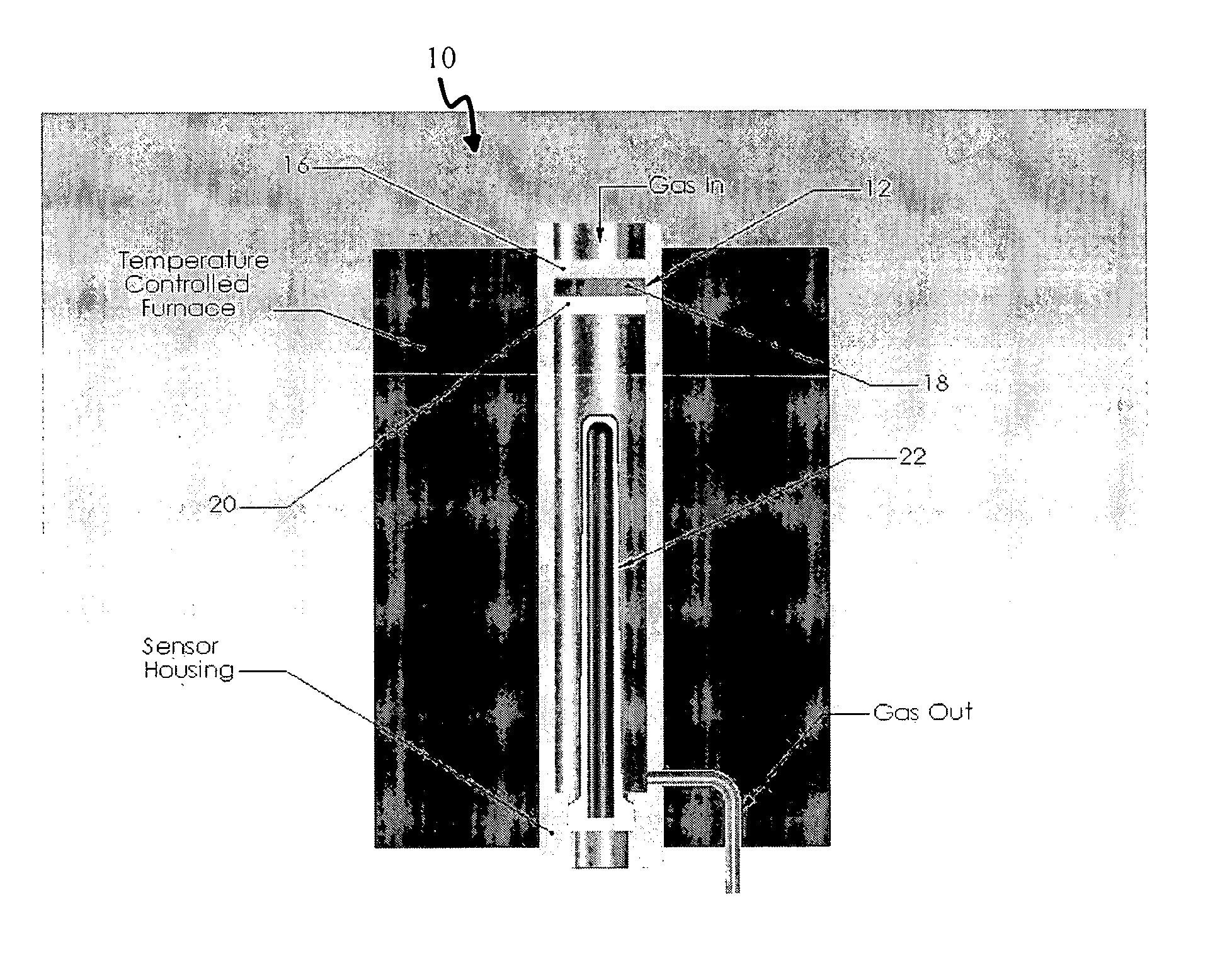
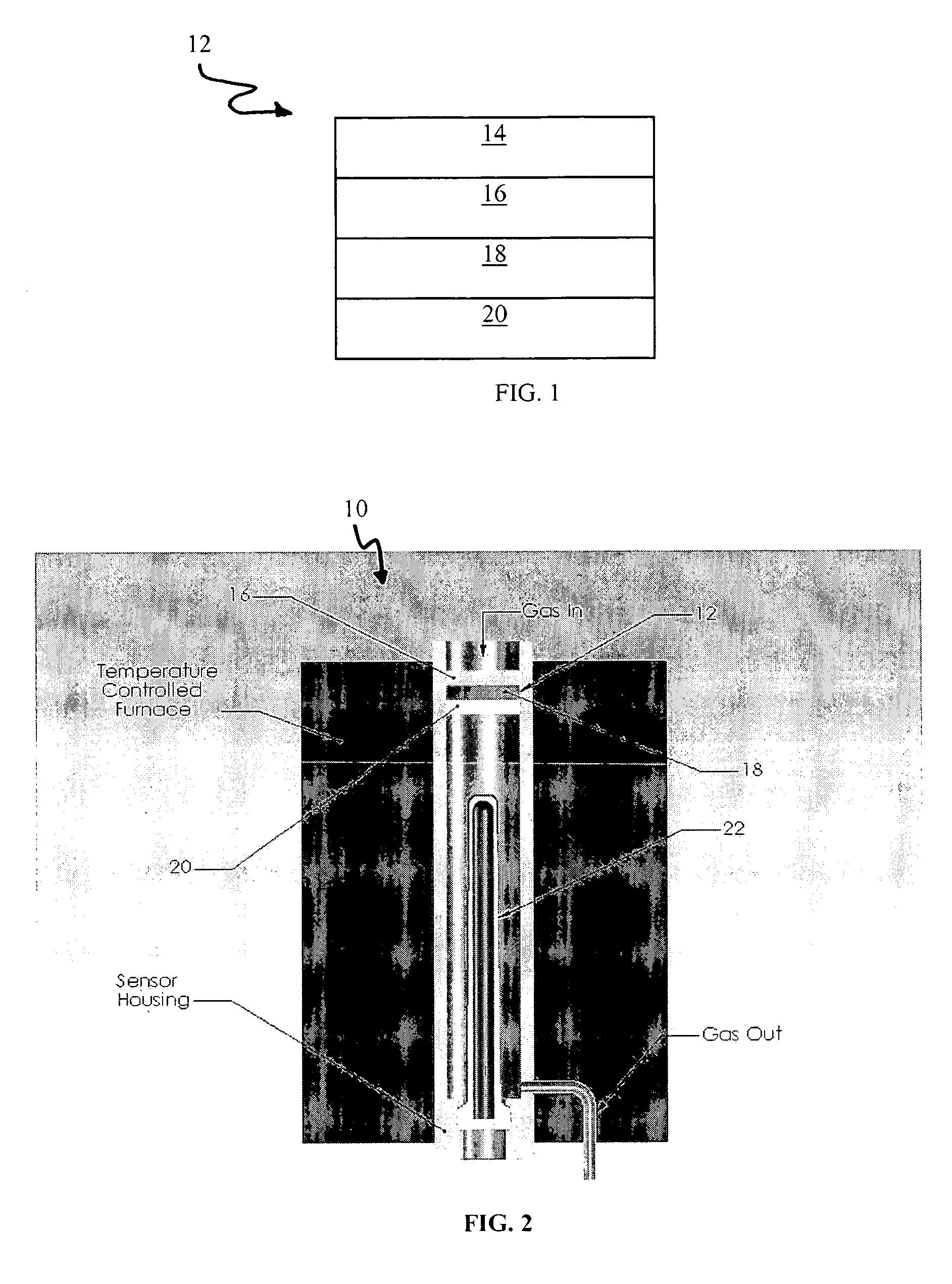
[0043] A NOx sensor 22 having a structure of the kind shown in FIG. 2 was constructed of a tubular electrolyte body fabricated by the addition of a binder to a commercially available 8 mole % Y2O3 doped zirconia powder. The binder / powder mixture was dispensed into a tooling followed by isostatic pressing at 25,000 psi. The ceramic portion was machined to final dimensions and then sintered at 1475° C. for two (2) hours. Next, the ceramic electrolyte was coated with electrodes. The inside of the tube along with a stripe on the outside of the tube (current collector) were coated with a platinum paste electrode material followed by firing at 1000° C. for one (1) hour. Then, the tip of the tube was coated with a tungsten oxide / zirconia mixture that contacted the platinum stripe current collector so that electrical contact was made. The electrode coating was dried and fired at high temperature to promote good adhesion.

[0044] The input assembly 12 was fabricated by using a ⅜″ diameter sta...

example 2

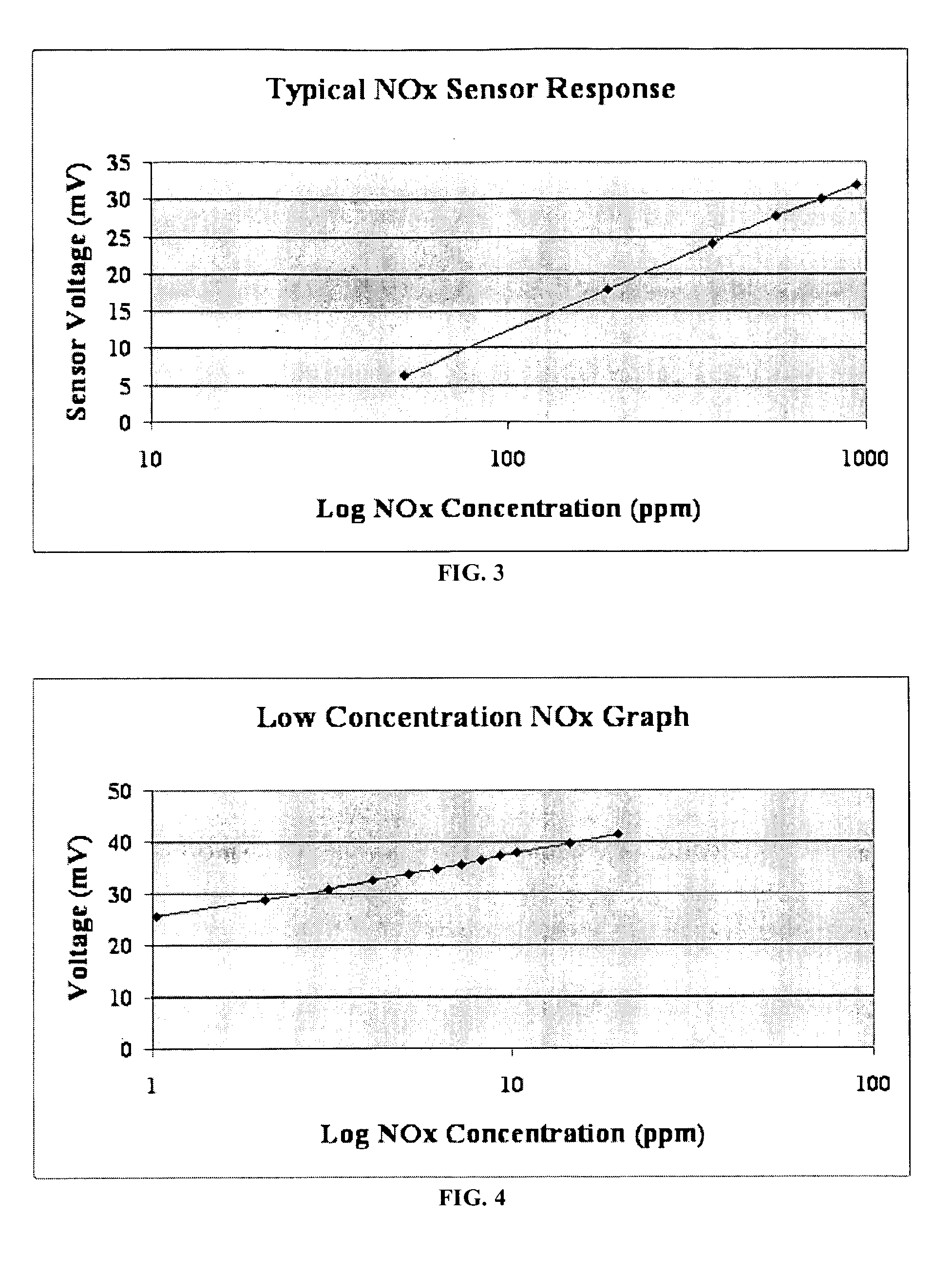
[0046] A NOx sensor fabricated as described in Example 1 was tested at low concentrations of NOx gases to demonstrate the low range capability of the present invention. Gases were mixed together using a four-channel mass flow controller system that enabled changing the NOx concentration in the gas stream and measuring the sensor voltage signal. A certified gas cylinder with a concentration of 20 ppm NO / balance nitrogen was used for this test. The concentration was varied by mixing this gas cylinder with gases from a nitrogen and oxygen cylinder. The concentration was varied in increments of 1 ppm from 1-20 ppm. A graph showing the voltage output signal as a function of NOx concentration is shown in FIG. 4.

example 3

[0047] The NOx sensor fabricated as described in Example 1 was also tested for sensor response time to demonstrate the apparatus' ability to function as part of a control system in a NOx removal device. Gases were mixed together using a four-channel mass flow controller system that enabled changing the NOx concentration in the gas stream and measuring the sensor voltage signal. The gas concentration was switched between 470 ppm and 940 ppm NOx at a flow rate of 500 cc / min. The voltage signal was monitored continuously using a data acquisition system with a sampling rate of three readings per second. The sensor response time is defined as a 90% step change of the total voltage signal when the concentration of the NOx gas is changed. A sensor response time curve is shown in FIG. 5 that indicates a sensor response time of 2.7 seconds when the NOx gas concentration is changed from 470 ppm to 940 ppm.


PUM


Abstract

The present invention is a method and apparatus for measuring the total NOx concentration in a gas stream utilizing the principles of a NOx sensor, i.e., mixed potential sensor. The exhaust gas is first conditioned by a catalyst assembly that converts the various species of nitrogen oxide gases present to a fixed steady state concentration ratio of NO2/NO, where NO2 is approximately 0-10% of the total NOx concentration present in the gas exhaust, thereby enabling the NOx sensor to generate a meaningful and reproducible determination of the concentration of total NOx present in the gas being measured. The catalyst assembly also functions to oxidize any unburned combustibles such as CH4, CO, etc., and remove potential contaminants such as SO2.

Description

RELATED APPLICATIONS [0001] This application claims priority to U.S. Provisional Patent Application No. 60 / 574,622, filed May 26, 2004, and is incorporated by reference herein.TECHNICAL FIELD [0002] The present invention relates in general to the measurement of NOx gases in exhaust streams generated from the combustion of hydrocarbons and particularly the combustion of diesel fuels in cars and trucks. BACKGROUND OF THE INVENTION [0003] One known NOx sensor is configured as a flat plate multilayer ceramic package design that includes two or more chambers. In the first chamber there are electrodes attached to an oxygen ion conducting electrolyte membrane, thereby forming an oxygen pump to remove the oxygen. In addition, NO2 is decomposed to NO and one-half O2. The free oxygen is removed in the first chamber so that theoretically the only gas that enters the second chamber is NO. Another oxygen pump is in the second chamber and is a NO decomposing element that removes the oxygen from t...

Claims


Application Information

Patent Timeline
IPC IPC(8): G01N27/26G01N31/00G01N33/00
CPCG01N27/4074G01N33/0037G01N33/0013Y02A50/20
Inventor NAIR, BALAKRISHNAN G.NACHLAS, JESSE A.MIDDLEMAS, MICHAEL
Owner EMISENSE TECH
Why Eureka
Try Eureka