Electric potential sensor

a potential sensor and electric current technology, applied in the field of electric potential sensors, can solve the problems of inability to accurately measure signals, inhibit or prevent accurate signal measurement, and high input impedance of electrical circuits with very high input impedance, etc., and achieve the effect of non-invasive and high-precision signal measuremen

Active Publication Date: 2012-09-11
THE UNIV OF SUSSEX
View PDF20 Cites 21 Cited by
  • Summary
  • Abstract
  • Description
  • Claims
  • Application Information

AI Technical Summary

Benefits of technology

[0009]The present invention seeks to overcome the problems described above and to provide a novel electric potential sensor which is capable of highly accurate and non-invasive signal measurement.
[0010]The present invention, at least in the preferred embodiments described below, also seeks to provide an electric potential sensor in which the signal to noise ratio is significantly enhanced.
[0015]input impedance enhancing means for providing a high input impedance to the sensor amplifier for increasing the sensitivity of the electrode to reduced electric potentials; and
[0017]According to the invention, the discrete pre-amplifier stage serves to increase the amplitude of the input measurement signal and thereby to increase the signal to noise ratio and enhance signal measurement. The discrete pre-amplifier stage may, for example, be provided by a high electron mobility transistor, or a FET arrangement.
[0021]The present invention thus aims to increase the signal to noise ratio either by increasing the amplitude of the signal or by decreasing the amplitude of the noise or both.

Problems solved by technology

However, electronic circuits with a very high input impedance tend to be unstable, and so practical devices are usually a compromise between achieving the necessary degree of sensitivity, providing the desired input impedance and ensuring an acceptable degree of stability.
Whilst these features assist in providing a sensor with high input impedance and a relatively stable operation, nevertheless, in situations where there may be weak capacitive coupling to, or a signal of small amplitude generated by, a source or sample under test, noise problems may still remain and may inhibit or prevent accurate signal measurement.
In this case, the measurement signal received by the sensor is attenuated by the capacitive potential divider formed by the coupling capacitance and the input capacitance and may be difficult to capture.

Method used


Image

  • Electric potential sensor
  • Electric potential sensor
  • Electric potential sensor

Examples


Embodiment Construction

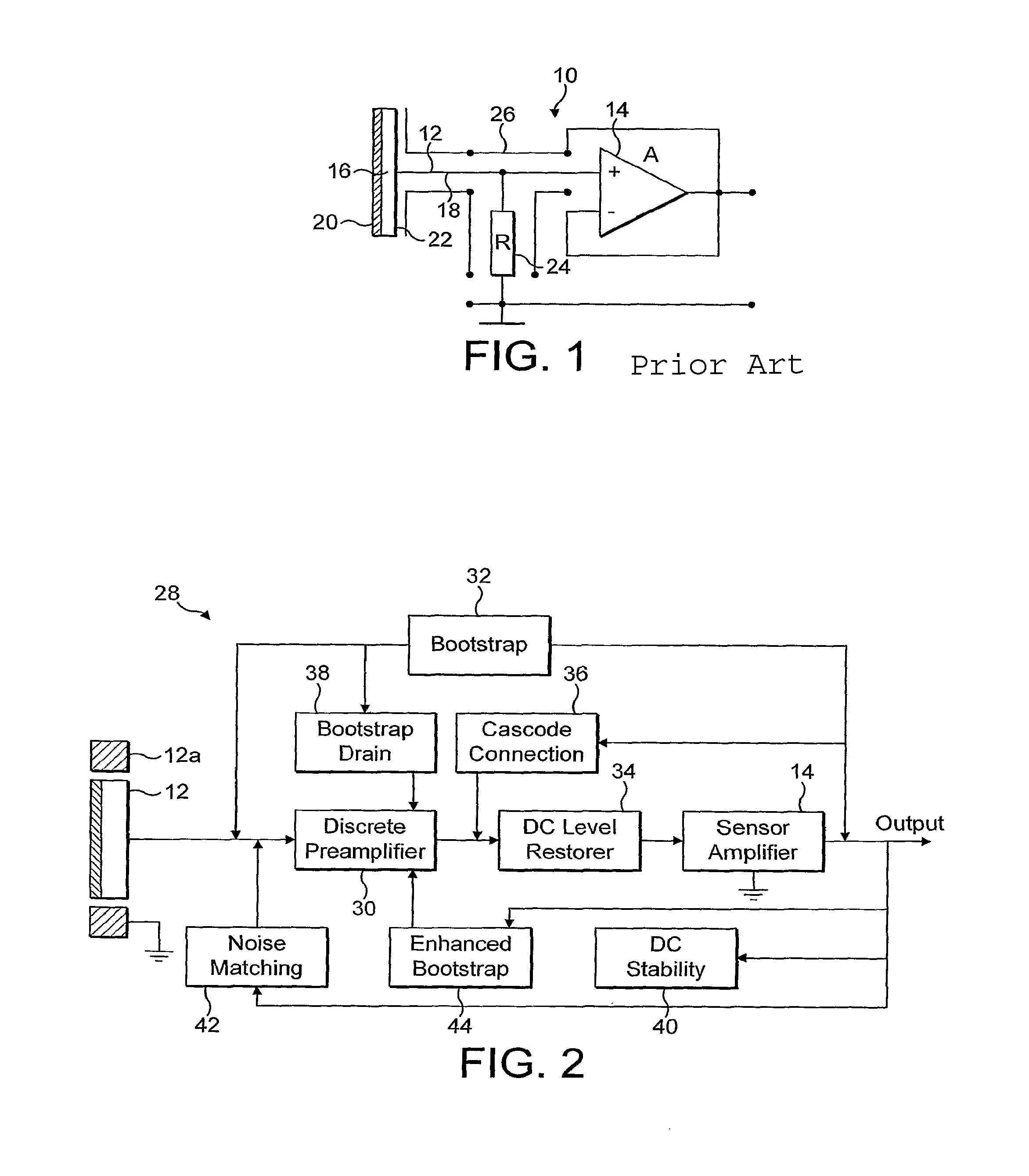
[0035]Referring to FIG. 1, an electrodynamic sensor as disclosed in International Patent Application No. WO 03 / 048789 will first be described.

[0036]As shown in FIG. 1, an eletrodynamic sensor 10 according International Patent Application number WO 03 / 048789 comprises a detection electrode 12 connected to the non-inverting input of a sensor amplifier 14. In use, the detection electrode 12 supplies a measurement signal to the sensor amplifier 14, whose output supplies an amplified detection signal as output.

[0037]The detection electrode 12 includes an electrode disc 16 mounted on a conductive stem 18, the electrode disc 16 comprising a surface oxide layer 20 on a substrate 22. The sensor amplifier 14 has a fixed input resistance 24, connected between the electrode 12 and the non-inverting input of the amplifier 14, to provide a steady input bias current to the amplifier 14. In practice, the input resistor 24 will generally have a high resistance of the order of 100 GΩs or greater. The...


PUM


Abstract

The present invention provides an electric potential sensor for the measurement of potentials non-invasively. The sensor comprises at least one detection electrode arranged for capacitive coupling with a sample under test and for generating a measurement signal, and a sensor amplifier adapted to receive the measurement signal as input and to supply an amplified detection signal as output. Input impedance enhancing means are included for providing a high input impedance to the sensor amplifier for increasing the sensitivity of the electrode to reduced electric potentials, and a discrete pre-amplifier stage is arranged to co-operate with the sensor amplifier to reduce the input capacitance of the amplifier.

Description

TECHNICAL FIELD[0001]The present invention concerns electric potential sensors for use for the measurement of potentials non-invasively in a wide variety of applications, for example in the fields of medical diagnostics and biometric sensing.BACKGROUND OF THE INVENTION[0002]In order to create a sensitive electrodynamic measuring device, it is customary to provide a high input impedance and thereby reduce the power of the input signal required to operate the device. However, electronic circuits with a very high input impedance tend to be unstable, and so practical devices are usually a compromise between achieving the necessary degree of sensitivity, providing the desired input impedance and ensuring an acceptable degree of stability.[0003]In International Patent Application No. WO 03 / 048789, an electrodynamic sensor is disclosed in which different circuit techniques are combined to achieve several orders of magnitude improvement in sensitivity, by comparison with previously known el...

Claims


Application Information

Patent Timeline
Patent Type & Authority Patents(United States)
IPC IPC(8): G01R27/26G01R19/00
CPCG01R29/12G01R19/0023A61B5/0408A61B5/0478A61B5/25A61B5/291A61B5/277
Inventor PRANCE, ROBERTHARLAND, CHRISTOPHER
Owner THE UNIV OF SUSSEX
Why Eureka
Try Eureka