Multilayer ceramic electronic component

Active Publication Date: 2020-12-24
MURATA MFG CO LTD
View PDF0 Cites 3 Cited by
  • Summary
  • Abstract
  • Description
  • Claims
  • Application Information

AI Technical Summary

Benefits of technology

The patent text describes a method for improving the adhesion force and preventing cracks in a multilayer ceramic electronic component. The method involves using a specific dielectric material with a preferred grain size in the outer layer of the component. By controlling the grain size in the outer layer, the adhesion force between the component and the outer electrode is improved, reducing the likelihood of cracks. Additionally, the thickness of the dielectric material in the corner portions of the component is increased to further enhance its impact resistance. Overall, this method provides a more robust and reliable multilayer ceramic electronic component.

Problems solved by technology

When the multilayer ceramic electronic component such as the multilayer ceramic capacitor is used under such an environment, there is a concern that moisture is likely to enter from an interface between an outer electrode and a ceramic element assembly, thus resulting in deterioration of reliability of moisture resistance.
As a result, there is a concern that the reliability of the moisture resistance of the multilayer ceramic electronic component is more likely to be deteriorated.
However, for example, a multilayer ceramic electronic component used for an electronic device or the like required in a market of in-vehicle devices or the like needs to have a larger capacitance, thus resulting in an increased size of the multilayer ceramic electronic component.
The increased size of the multilayer ceramic electronic component leads to an increased weight of the multilayer ceramic electronic component, with the result that a greater impact is applied to a corner portion of the outer electrode during handling.
Accordingly, an impact resistance at the corner portion of the multilayer ceramic electronic component becomes weak.

Method used


Image

  • Multilayer ceramic electronic component
  • Multilayer ceramic electronic component
  • Multilayer ceramic electronic component

Examples


experiment examples

[0175

[0176]In accordance with the above-described manufacturing method, a multilayer ceramic capacitor was produced as a multilayer ceramic electronic component, and was checked through impact resistance test and moisture resistance load test on a corner portion thereof.

Specification of Ceramic Capacitor Used for Example

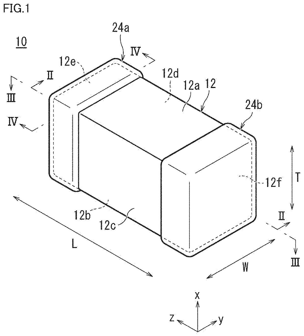
[0177]Size L×W×T (designed value): about 3.310 mm×about 2.645 mm×about 2.645 mm[0178]Ceramic material: BaTiO3 [0179]Capacitance: about 10 μF[0180]Rated voltage: about 100 V

Information on Outer Layer Portions

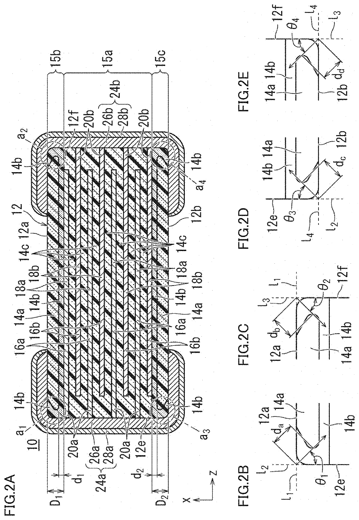
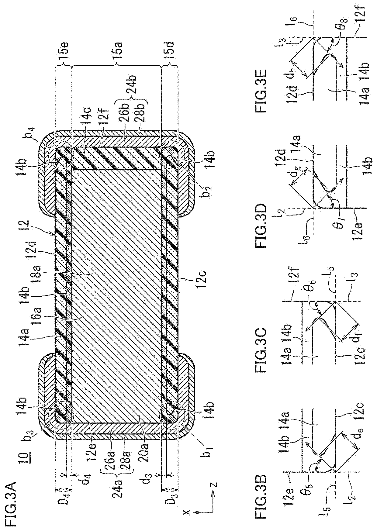
[0181]Dy and Mg were included in a dielectric sheet at a portion corresponding to a portion of the dielectric layer in which grain sizes are to be made small (portion thereof in which grain growth is to be reduced or prevented). It should be noted that an amount of Dy contained therein was about 20 times as large as an amount of Mg in a molar ratio.

[0182]In the dielectric sheet for the region of the dielectric layer in which grain sizes are to be made small, Dy an...


PUM

PropertyMeasurementUnit
Fractionaaaaaaaaaa
Fractionaaaaaaaaaa
Thicknessaaaaaaaaaa

Abstract

A multilayer ceramic electronic component includes a multilayer body including an inner layer portion in which inner electrode layers face each other, first and second outer layer portions respectively on first and second main surface sides. At the first and second outer layer portions, a grain size in the dielectric layer located on the inner layer portion side and a grain size in the dielectric layer located along each of respective ridgeline portion sides on which respective ones of the first and second main surfaces cross both end surfaces is smaller than the grain size in the dielectric layer located on the respective first and second main surface sides.

Description

CROSS REFERENCE TO RELATED APPLICATIONS[0001]This application claims the benefit of priority to Japanese Patent Application No. 2019-116044 filed on Jun. 24, 2019. The entire contents of this application are hereby incorporated herein by reference.BACKGROUND OF THE INVENTION1. Field of the Invention[0002]The present disclosure relates to a multilayer ceramic electronic component.2. Description of the Related Art[0003]In recent years, since a multilayer ceramic electronic component such as a multilayer ceramic capacitor has attained a small size and a large capacitance, a ratio of an effective layer defined by an inner electrode has become large. Moreover, in view of such a background, the multilayer ceramic electronic component has begun to be used under an environment (for example, a high humidity environment) more severe than those for conventional ones. When the multilayer ceramic electronic component such as the multilayer ceramic capacitor is used under such an environment, the...

Claims


Application Information

Patent Timeline
IPC IPC(8): H01G4/30H01G4/012H01G4/248H01G4/008H01G4/232
CPCH01G4/1227H01G4/248H01G4/2325H01G4/012H01G4/008H01G4/30H01G4/1209H01G4/1218H01G4/224H01G4/232
Inventor OOSAWA, WATARU
Owner MURATA MFG CO LTD
Why Eureka
Try Eureka