
Reciprocating blade apparatus and handheld working machine

Active Publication Date: 2020-12-31
YAMABIKO CORP
View PDF0 Cites 2 Cited by
  • Summary
  • Abstract
  • Description
  • Claims
  • Application Information

AI Technical Summary

Benefits of technology

The present invention provides a reciprocating blade apparatus that can improve the maintenance and replacement of blades by enabling them to be detached and attached without taking apart the apparatus. This reduces the workload and time to sharpen and replace the blades. The technical effect is improved efficiency in the maintenance and replacement of blades.

Problems solved by technology

When the blades mounted to the apparatus are sharpened, it is necessary to move the blades during the intermission of the work, which is very troublesome.
However, it takes a lot of work and time to take apart the apparatus to remove the blades and assemble the apparatus again.
Moreover, when the blades of the reciprocating blade apparatus are no longer able to be used due to wear or damage, it is necessary to replace the blades.
In this case, if it is necessary to take apart and assemble the apparatus to replace the blades, it also takes a lot of work and time.

Method used


Image

  • Reciprocating blade apparatus and handheld working machine
  • Reciprocating blade apparatus and handheld working machine
  • Reciprocating blade apparatus and handheld working machine

Examples


Embodiment Construction

[0019]Hereinafter, an embodiment of the present invention will be described with reference to the drawings. The same reference numbers in the different drawings indicate the same functional parts, and therefore repeated description for each of the drawings is omitted.

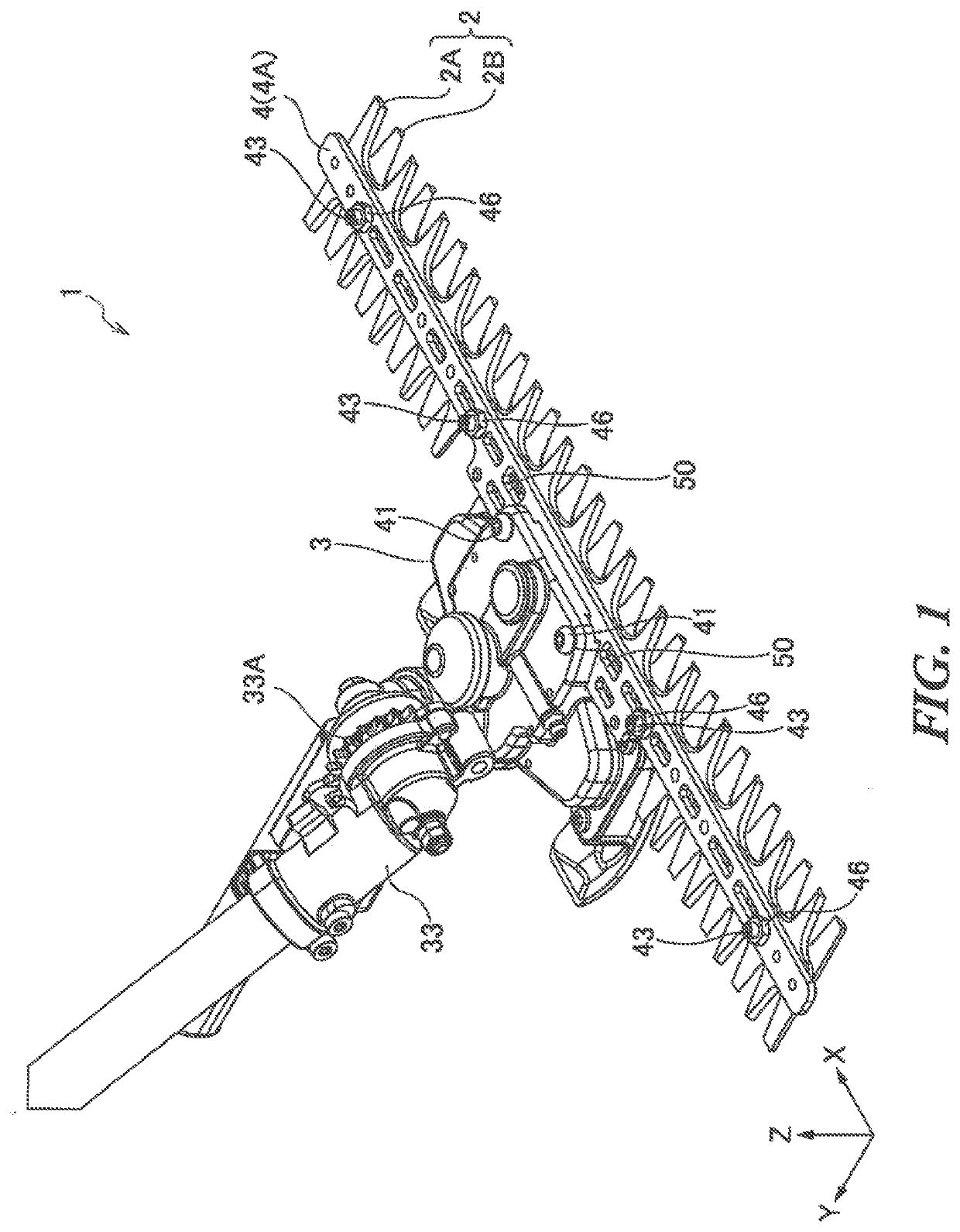
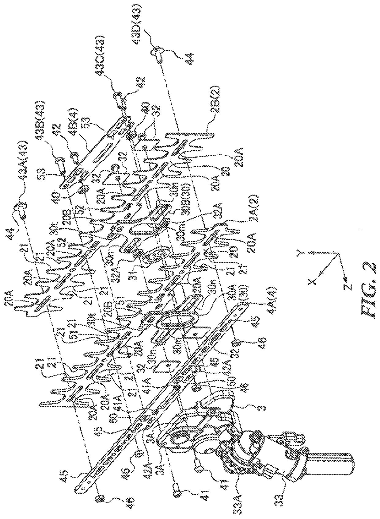
[0020]As illustrated in FIGS. 1 and 2, a reciprocating blade apparatus 1 includes a pair of reciprocating blades 2 (hereinafter referred to as “blade member”), a transmission case 3, and a blade support member 4. The reciprocating blade apparatus 1 is configured to cut and mow plants and so forth by sliding and reciprocating the blade member 2 relative to one another.

[0021]The blade member 2 includes two blades 2A and 2B made of metal plates which are stacked in the thickness direction (Z direction in the drawings). Each of the blades 2A and 2B of the blade member 2 includes a base 20 as a flat plate extending in the longitudinal direction (X direction in the drawings) and a plurality of teeth 21 protruding in the direc...


PUM


Abstract

A reciprocating blade apparatus includes: a pair of reciprocating blades stacked on one another in a thickness direction, each of which includes a base as a flat plate extending in a longitudinal direction, and a plurality of teeth protruding in a direction intersecting the longitudinal direction; a transmission case including a reciprocating member having a joint detachably coupled to the base, the reciprocating member being reciprocally supported in the longitudinal direction; and a blade support member attached to the transmission case and configured to sandwich bases of the pair of reciprocating blades therebetween to allow the pair of reciprocating blades to move in the longitudinal direction. The blade support member holds a space to accommodate the pair of reciprocating blades and is independently attached to the transmission case. The pair of reciprocating blades is detachably attached to the blade support member.

Description

CROSS-REFERENCE TO RELATED APPLICATIONS[0001]The present application claims priority from Japanese Patent Application No. 2019-121825 filed on Jun. 28, 2019, and the entire contents of which are hereby incorporated by reference.BACKGROUND1. Technical Field[0002]The present invention relates to a reciprocating blade apparatus, and a handheld working machine equipped with the reciprocating blade apparatus.2. Related Art[0003]As a handheld working machine for cutting or clipping branches and leaves, there has been generally known a hedge trimmer equipped with a reciprocating blade apparatus having reciprocating blades, like a hair clipper. Meanwhile, as a handheld working machine for cutting grass on the ground, there has been generally known a brush cutter equipped with rotary blades or nylon cutters.[0004]The handheld working machine for cutting branches and leaves is required to produce little scattering substances during the work, in order to ensure the safety of the worker and the...

Claims


Application Information

Patent Timeline
IPC IPC(8): A01G3/047
CPCA01G2003/0461A01G3/047A01D34/10A01D34/13A01G3/053A01G3/0475
Inventor SHIMIZU, KUNIOKODAMA, HISAO
Owner YAMABIKO CORP
Features
  • Generate Ideas
  • Intellectual Property
  • Life Sciences
  • Materials
  • Tech Scout
  • Unparalleled Data Quality
  • Higher Quality Content
  • 60% Fewer Hallucinations
Learn More